
Production of the second-generation Citroën C4 Picasso began in 2013, following the debut of the Technospace concept car—the prototype for the new minivan—at the Geneva Motor Show in March of that year. The vehicle utilizes the new EMP2 modular platform, featuring a wheelbase extended to 2785 mm. In this article, we provide a detailed overview of the fuse box diagrams for the Citroën C4 Picasso (second generation; EMP2 platform; B78 code) for the 2014–2020 model years, including the seven-seat Grand C4 Picasso modification.

Below are the locations and photos of the fuse distribution boxes. The fuses responsible for the “Cigarette Lighter” and “Fuel Pump” are highlighted in bold.
Passenger Compartment
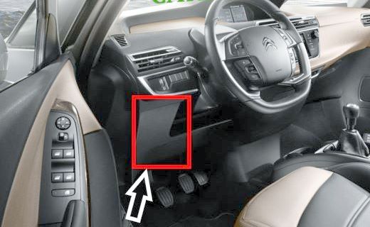
Located in the lower dashboard on the driver's side.
Main Fuse Box
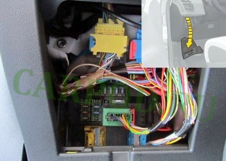
Access example.
Type 1
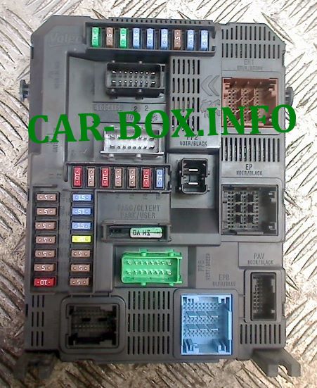
General view of the Citroën C4 Picasso passenger compartment fuse box.
| Diagram | ||
|---|---|---|
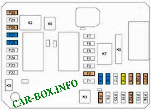
|
||
| No. | Description | Amps |
| F2 | Manual headlight leveling | 5 |
| F8 | Steering wheel control module | 5 |
| F12 | Remote engine start module | 5 |
| F15 | 12 V power outlet in the trunk | 15 |
| F16 | Front 12 V power outlet | 15 |
| F18 | Infotainment touchscreen display, audio and navigation systems, CD player, USB, and auxiliary ports | 20 |
| F19 | Rain and ambient light sensor | 5 |
| F20 | Airbags | 5 |
| F21 | Instrument cluster | 5 |
| F26 | Horn | 15 |
| F27 | Front and rear window washer pump | 15 |
| F28 | START/STOP button | 5 |
| F30 | Rear window wiper | 15 |
Type 2
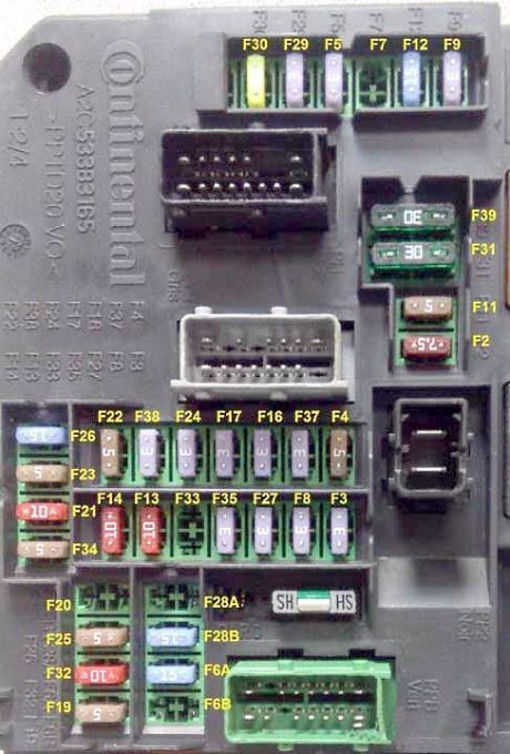
Passenger compartment fuse assignment.
| Diagram | ||
|---|---|---|
|
||
| No. | Description | Amps |
| 8 | Alarm siren, alarm control module | 3 |
| 9 | Steering column switch assembly | 3 |
| 11 | Electronic Stability Program (ESP) control module, main alarm switching unit, electronic key scanner | 5 |
| 12 | Dual brake pedal switch | 15 |
| 13 | Front cigarette lighter | 10 |
| 14 | Rear cigarette lighter socket | 10 |
| 16 | Map lights, glove box illumination | 3 |
| 17 | Sun visor vanity mirror illumination, map lights | 3 |
| 19 | Instrument cluster | 5 |
| 20 | Automated manual transmission gear selector | 5 |
| 21 | Audio and climate control system panel | 10 |
| 22 | Displays, parking assist sensors | 5 |
| 23 | Engine compartment fuse box | 5 |
| 24 | Rain and ambient light sensor | 3 |
| 25 | Airbag and seat belt pretensioner module | 15 |
| 26 | - | 15 |
| 27 | Dual brake pedal switch | 3 |
| 28 | Car audio system (optional) | 15 |
| 29 | Thumbwheel switch | 3 |
| 30 | Rear window wiper | 20 |
| 31 | Central locking, front and rear door lock actuators | 30 |
| 32 | Rearview camera power supply, audio amplifier | 10 |
| 33 | Driver's seat memory module | 3 |
| 34 | Electronic power steering relay | 5 |
| 35 | - | 3 |
| 37 | Driver's door power window/mirror switch, auto-dimming interior rearview mirror | 3 |
| 38 | Headlight leveling switch, auto-dimming interior rearview mirror | 3 |
| 39 | - | 30 |
Auxiliary Fuse Box
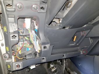
An auxiliary fuse box is located beneath the main unit. Removing the lower trim panel is recommended for easier access.
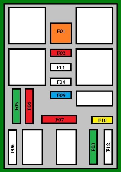
Diagram. |
||
| No. | Description | Amps |
| 1 | Rear window defogger | 40 |
| 2 | Power folding mirrors | 20 |
| 5 | Sunroof | 30 |
| 6 | 12 V power outlet, rear multimedia system | 20 |
| 7 | 230 V power outlet | 20 |
| 9 | Heated seats | 25 |
| 10 | Trailer tow module | 20 |
| 11 | HVAC blower motor | 20 |
| 12 | Power window motors | 30 |
Engine Compartment
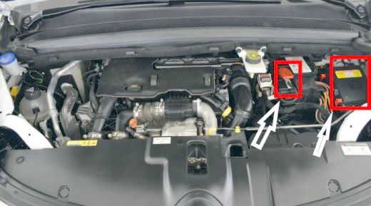
There are two fuse boxes: the main fuse box located on the right side of the battery, and the high-current fuse block attached to the positive battery terminal.
Main Fuse Box
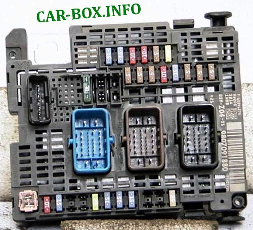
An example is shown in the photo.
| Diagram | ||
|---|---|---|

|
||
| No. | Description | Amps |
| 1 | Engine control module (ECM) - power management unit | 15 |
| 2 | Cooling fan control module | 5 |
| 3 | Engine management | 5 |
| 4 | Centralized voltage regulation device - reversible alternator | 5 |
| 5 | Engine control module (ECM) | 15 |
| 6 | Engine control module (ECM) | 20 |
| 7 | Engine control module (ECM) | 10 |
| 8 | Engine control module (ECM) | 10 |
| 9 | Power tailgate actuator | 30 |
| 11 | Protection and switching module - headlight leveling module - DPF additive pump | 15 |
| 12 | Parking assist control module with "City Park" system - reversible seat belt retractor | 5 |
| 13 | Empty | |
| 14 | Front and rear window washer pump - A/C compressor | 25 |
| 15 | Empty | |
| 17 | Built-in Systems Interface (BSI) | 10 |
| 18 | Audio amplifier | 25 |
| 19 | Windshield wiper motor (low/high speed) | 30 |
| 15 | Distance alert control module - OBD2 diagnostic connector - engine coolant level switch - electronic power steering control module | 5 |
| 20 | Front and rear window washer pump | 15 |
| 21 | Headlight washer pump | 20 |
| 22 | Alarm system | 15 |
| 23 | Left halogen high-beam headlight | 15 |
| 24 | Right halogen high-beam headlight | 15 |
| 25 | Empty | |
| 26 | Empty | |
| 27 | Left headlight with shutter | 5 |
| 28 | Right headlight with shutter | 5 |
| 29 | Starter motor | 30 |
| 30 | Engine management | 30 |
| 9 | Electronic immobilizer / anti-theft system | 10 |
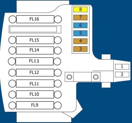
High-Current Fuse Block
Located on the positive battery terminal.
| Diagram | ||
|---|---|---|
|
||
| 1 | Main fuse board | 80 |
| 2 | 70 | |
| 3 | Electronic Stability Program (ESP) | 50 |
| 4 | Alarm control module | 15 |
| 5 | Electronic Stability Program (ESP) | 40 |
| 6 | Empty | |
| 7 | Empty | |
| 8 | Electronic power steering (EPS) | 80 |
| 9 | Main fuse board | 125 |
| 10 | Built-in Systems Interface (BSI) | 60 |
| 11 | Passenger compartment fuse box | 40 |
| 12 | 60 | |
| 13 | 60 | |
| 14 | Empty | |
| 15 | Empty | |
| 16 | Glow plug pre-heating/post-heating module | 70 |
| 17 | Empty | |
| 18 | Empty | 5 |
| 19 | 40 | |
| 20 | Auxiliary 12 V power outlet | 30 |
| 21 | Empty | 5 |
| 23 | Dual-speed cooling fan control module | 60 |
| 24 | HVAC blower motor | 40 |
| 25 | Empty | |
| 26 | Automated manual transmission control module | 30 |
| 27 | Protection and switching module | 80 |
| 22 | Battery charge status module | 5 |

Merci pour votre aide