
The Citroën C4 Picasso is a compact multi-purpose vehicle (MPV). Featuring a 2.73-meter wheelbase, it offers a spacious cabin and generous cargo capacity. Built on the PSA PF2 platform shared with the C4 and Peugeot 307, the five-seat MPV officially debuted in January 2007, shortly after the launch of the seven-seat Grand C4 Picasso. This article provides detailed fuse box diagrams and circuit assignments for the first-generation Citroën C4 Picasso (UD chassis) and Grand C4 Picasso (UA chassis) produced from 2006 through 2013.
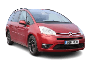
Below are the component location diagrams, photographs, and fuse assignment tables for the power distribution boxes. Fuses for the “Cigarette lighter” and “Fuel pump” are highlighted in bold text.
In the engine compartment
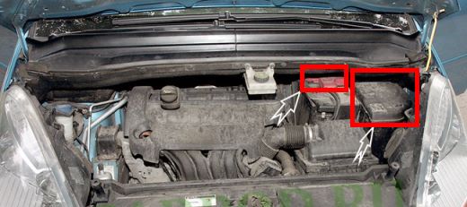
The engine compartment houses two fuse modules: the main engine compartment fuse box located to the right of the battery, and the battery power unit mounted directly on the positive terminal.
Main fuse box
This unit was fitted in several configurations depending on vehicle specification.
Type 1
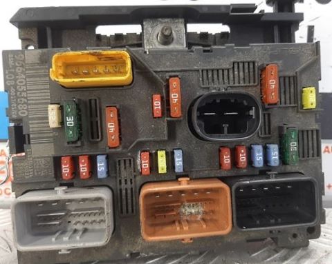
Overview.
| Diagram | ||
|---|---|---|
|
||
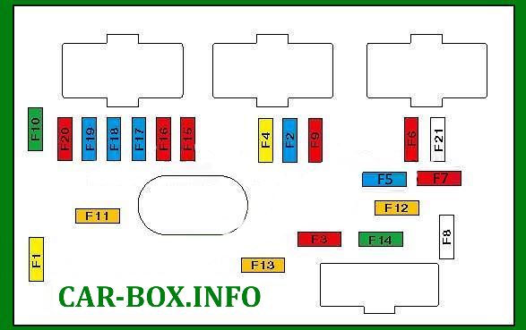
| No. | Protected Circuit / Component | Rating (A) |
| F1 | Engine management ECU | 20 |
| F2 | Horn | 15 |
| F3 | Windscreen / rear window washer pump | 10 |
| F4 | Headlamp washer pump | 20 |
| F5 | Engine management systems | 15 |
| F6 | Adaptive bi-xenon headlamps, directional headlamp control module, clutch pedal switch, Safety Switching Unit (SSU) | 10 |
| F7 | Automatic transmission ECU, coolant level sensor, power steering ECU | 10 |
| F8 | Starter motor relay | 15/20 |
| F9 | Brake pedal switch (brake lamp switch) | 10 |
| F10 | Engine management actuators | 30 |
| F11 | Blower motor fan | 40 |
| F12 | Windscreen wipers | 30 |
| F13 | Built-in Systems Interface (BSI) | 40 |
| F14 | Coolant pump | 30 |
| F15 | Right main beam headlamp | 10 |
| F16 | Left main beam headlamp | 10 |
| F17 | Left dipped beam headlamp | 15 |
| F18 | Right dipped beam headlamp | 15 |
| F19 | Engine management system sensors and actuators | |
| F20 | Engine management system | 15 |
| F21 | Fuel filter heater | 10 |
Type 2

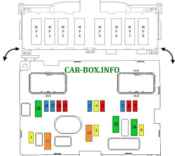
Overview.
| Diagram | ||
|---|---|---|
|
||
| No. | Protected Circuit / Component | Rating (A) |
| 1 | Engine management ECU | 20 |
| 2 | Horn | 15 |
| 3 | Windscreen / rear window washer pump | 10 |
| 4 | Headlamp washer pump | 20 |
| 5 | Fuel pump fuse | 15 |
| 6 | Adaptive bi-xenon headlamps, directional headlamp control module, clutch pedal switch, Safety Switching Unit (SSU) | 10 |
| 7 | Automatic transmission ECU, coolant level sensor, power steering ECU | 10 |
| 8 | Starter motor relay | 15 / 20 |
| 9 | Brake pedal switch (brake lamp switch) | 10 |
| 10 | Engine management actuators | 30 |
| 11 | Rear climate control blower fan | 40 |
| 12 | Windscreen wipers | 30 |
| 13 | Built-in Systems Interface (BSI) | 40 |
| 14 | Turbocharger boost pressure solenoid valve, exhaust gas heat recovery system unit | 30 |
| 15 | Right main beam headlamp | 10 |
| 16 | Left main beam headlamp | 10 |
| 17 | Left dipped beam headlamp | 15 |
| 18 | Right dipped beam headlamp | 15 |
| MAXI Fuses | ||
| MF1 | Anti-lock Braking System (ABS) / ESP module | 30 |
| MF2 | 30 | |
| MF3 | Electric Parking Brake (EPB) control module | 30 |
| MF4 | Unassigned | - |
| MF5 | 20 | |
| MF6 | Heating, ventilation, and air conditioning (HVAC) system | 50 |
| MF7 | 50 | |
| MF8 | Pneumatic suspension control module | 50 |
Battery Power Fuses
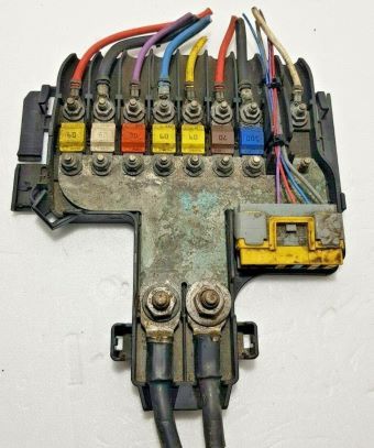
Mounted on the battery positive terminal module.
| Diagram | ||
|---|---|---|
| No. | Protected Circuit / Component | Rating (A) |
| Type 1 | ||

|
||
| F1 | Automatic transmission gear selector actuator (where fitted) | 5 |
| F2 | Brake lamp switch (brake pedal sensor) | 5/15 |
| F3 | Battery Monitoring Sensor (BMS) | 5 |
| F4 | ABS / ESP system processor supply | 20/30 |
| F5 | 5/30 | |
| F6 | Transmission Control Module (TCM) | 20/70 |
| F7 | Electric power steering unit | 100 |
| F8 | Engine cooling fan motor | 50 |
| F9 | 30 | |
| F10 | ABS hydraulic unit | 30 |
| F11 | 30 | |
| F12 | Unassigned | |
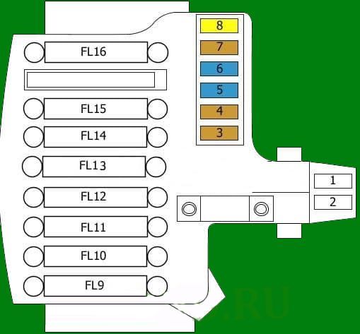
| Type 2 | ||
|
||
|
||
| FL9 | Built-in Systems Interface (BSI) main supply | 60 |
| FL10 | Electric power steering unit | 80 |
| FL11 | Transmission Control Module (TCM) | 30 |
| FL12 | Engine cooling fan assembly | 60 |
| FL13 | Built-in Systems Interface (BSI) secondary supply | 60 |
| FL14 | Glow plug control module | 70 |
| FL15 | Relay protection box 3 | 100 |
| FL16 | Unassigned | |
| 1 | Unassigned | |
| 2 | Unassigned | |
| 3 | Battery Monitoring Sensor (BMS) | 5 |
| 4 | Transmission Control Module (TCM) feed | 5 |
| 5 | Data Link Connector (DLC / OBD-II port) | 5/15 |
| 6 | Transmission Control Module (TCM) ignition feed | 15 |
| 7 | ABS control module | 5 |
| ESP control module | ||
| 8 | Rear 12V auxiliary power outlet | 20 |
In the passenger compartment
The interior features two fuse distribution panels configured to protect passenger compartment electrical systems.
Main interior fuse box

Located at the lower driver's side of the dashboard. Trim panels must be unclipped to gain access.
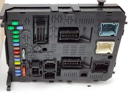
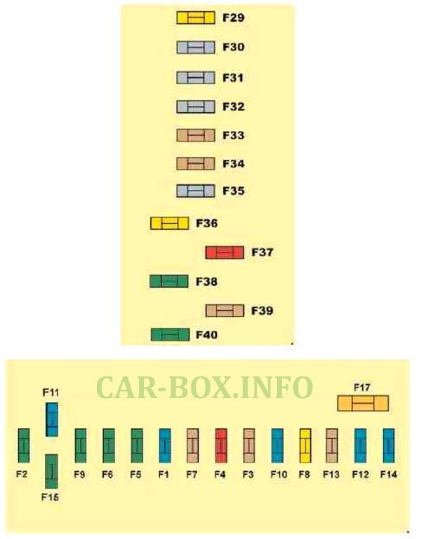
Overview of the main interior fuse panel.
| Diagram | ||
|---|---|---|
|
||
| No. | Protected Circuit / Component | Rating (A) |
| F1 | Rear window wiper motor | 15 |
| F2 | Central locking system | 30 |
| F3 | Supplemental Restraint System (SRS / Airbags) ECU | 5 |
| F4 | Infotainment head unit, electrochromic rearview mirror, diesel particulate filter (DPF) ECU, OBD-II diagnostic socket, climate control panel, headlamp leveling module | 10 |
| F5 | Front power window modules, driver door master control panel, panoramic sunroof blind | 30 |
| F6 | Rear power windows | 30 |
| F7 | Interior courtesy lamps, cooled glovebox light, audio unit | 5 |
| F8 | Multifunction display, audio system, steering wheel switch module, infotainment unit, Tire Pressure Monitoring System (TPMS) ECU, alarm ECU, trailer module | 20 |
| F9 | Cigarette lighter / front 12V power outlet, infotainment system, luggage compartment lamp, audio unit | 30 |
| F10 | Pneumatic suspension control module | 15 |
| F11 | Brake pedal switch, ignition switch circuit | 15 |
| F12 | Parking assistance ECU, automatic rain/light sensor module, power passenger seat, Lane Departure Warning System (AFIL), Hi-Fi audio amplifier, trailer socket | 15 |
| F13 | Engine Switching Unit (BSM), driver power seat memory unit | 5 |
| F14 | Air conditioning control panel, Bluetooth hands-free unit, automatic transmission gear selector, airbag ECU, instrument cluster display | 15 |
| F15 | Central locking actuator circuit | 30 |
| F17 | Heated rear window element | 40 |
| F29 | Heated seats module | 20 |
| F30 | Unassigned | |
| F31 | Trailer interface unit | 40 |
| F32 | Rear 12V auxiliary power socket | 15 |
| F33 | Parking assist ECU, rain and light sensor unit, power passenger seat, Lane Departure Warning System (AFIL), audio amplifier | 5 |
| F34 | Trailer wiring connector supply | 5 |
| F35 | Unassigned | |
| F36 | Hi-Fi audio amplifier | 20 |
| F37 | Air conditioning module, illumination control switch | 10 |
| F38 | Driver electric seat power supply | 30 |
| F39 |
|
5 |
| F40 | Front passenger electric seat power supply, panoramic sunroof module | 30 |
Auxiliary BFH3 Fuse Panel
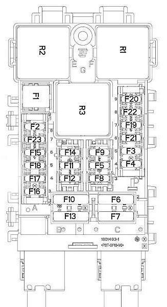
Mounted directly below the main interior fuse box.
| Diagram | ||
|---|---|---|
|
||
| No. | Protected Circuit / Component | Rating (A) |
| F3 | Passenger compartment fuse box 5 (cab chassis / utility variant) | 15 |
| F4 | 12V auxiliary socket for rear multimedia equipment | 15 |
| F5 | Rear power window motors | 30 |
| F6 | Front power window motors | 30 |
| F7 | Heated seats module | 2 |
| F8 | HVAC blower fan motor | 20 |
| F9 | Power tailgate motor unit | 30 |
| F10 | Driver seat belt pyrotechnic retractor pretensioner | 40 |
| F11 | Trailer control module | 5 |
| F12 | Driver power seat / seat massage module | 30 |
| F13 | Passenger seat belt pyrotechnic retractor pretensioner | 40 |
| F14 | Front passenger power seat / seat massage system module | 30 |
| F15 | Panoramic sunroof blind motor | 25 |
| F16 | Driver door multiplex switch assembly (power window / mirror controls) | 5 |
| F17 | Exterior mirror puddle lights and seat memory ECU | 10 |
| F18 | Hi-Fi audio system amplifier | 25 |
| F19 | Spare fuse slot | - |
| F20 | Power tailgate ECU | 7.5 |
| F21 | Keyless Entry and Start (ADML) unit | 3 |
| F2 | Heated exterior rear-view mirrors | 7.5 |
| F22 | 230V AC power outlet unit | 20 |
| F23 | Unassigned | - |
| R1 | 230V AC socket relay | - |
| R2 | 12V auxiliary socket relay | - |
| R3 | Unassigned | - |
| F1 | Heated rear window element (located on rear of module) | 40 |

finally a brilliant diagram thank you