The official premiere of Citroen C4 took place at the Paris Motor Show in 2004. The car was produced in several body types, of which a five-door hatchback and a "coupe" (so Citroen positions the three-door version of the hatchback) were available on the Russian market. In this article, we will take a detailed look at the fuse box diagrams for the Citroen C4 (1 generation; LA - three-door body, LS - five-door body) 2004, 2005, 2006, 2007, 2008 and 2009, 2010, 2011 years of manufacture.

Here you will find the locations and photos of distribution boxes. The fuses responsible for the “Cigarette lighter” and “Fuel Pump” are highlighted in bold.
In the passenger compartment

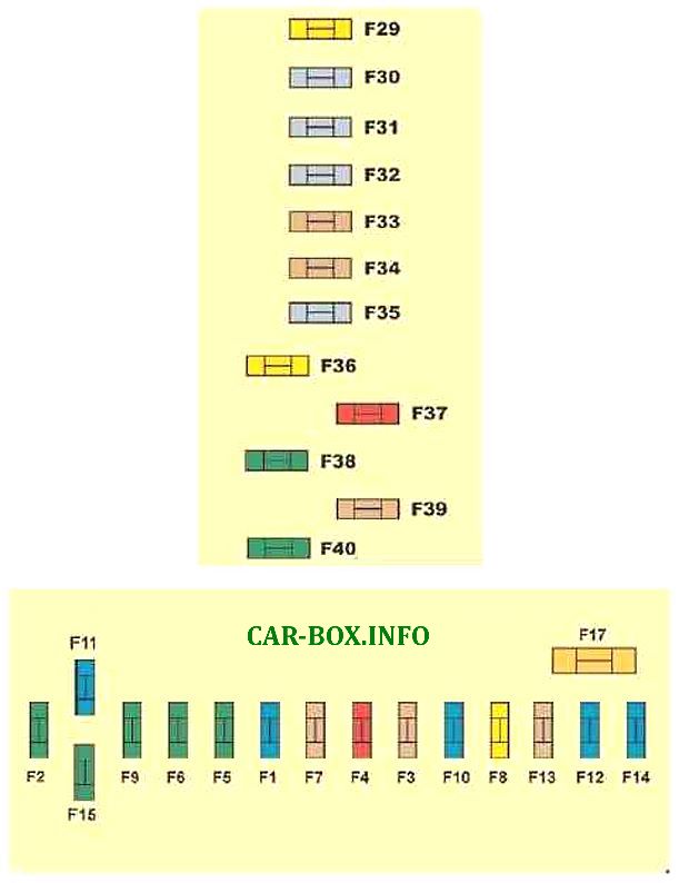
The distribution box is located on the driver's side of the dashboard, behind the protective cover.

General view of the Citroen C4 interior fuse box.
| Diagram | ||
|---|---|---|
|
||
| No. | Description | A |
| F1 | Rear windshield wiper. | 15 |
| F2 | Central locking - blocking. | 30 |
| F3 | Airbags and pretensioners. | 5 |
| F4 | Diagnostic connector - Stop light switch - Rearview mirror - Dynamic stabilization system (ESP) - Water level sensor - Diesel fuel additives - Clutch pedal contactor (ESP, cruise control and speed limiter. | 10 |
| F5 | Front window lifters - Heated and power door mirrors. | 30 |
| F6 | Rear power windows. | 30 |
| F7 | Interior lampshades | 5 |
| F8 | Car radio - NaviDrive - Steering wheel controls - Display - Security alarm system - 12V front socket - Trailer socket - Driving school module | 20 |
| F9 | Citroen C4 cigarette lighter fuse - Rear 12V power outlet. | 30 |
| F10 | Tire pressure sensors - BVA - STOP contactor. | 15 |
| F11 | Anti-theft steering lock - Diagnostic connector - Particulate filter. | 15 |
| F12 | Seat adjustment - Signal warning for unintentional crossing of the marking line - Parking sensors. | 15 |
| F13 | Rain and light sensor - Electronically controlled automatic transmission - Engine control unit. | 5 |
| F14 | Air conditioning - Instrument panel - Tachometer - Airbags and pretensioners -Trailer jack - Bluetooth phone. | 15 |
| F15 | Central locking system | 30 |
| F16 | SHUNT | |
| F17 | Rear window heater. | 40 |
| F29 | Seat heater. | 20 |
| F33 | Parking assist system, automatic activation of the windshield wiper and lights. | 4 |
| F36 | Hi-fi amplifier. | 20 |
| F37 | Air conditioning. | 10 |
| F38 | Power driver's seat. | 30 |
| F39 | Filling tank cover | 5 |
| F40 | Power passenger seat, panoramic sunroof. | 30 |
In the engine compartment
There are three distribution boxes here, which are responsible for protecting the vehicle's electrical circuits.
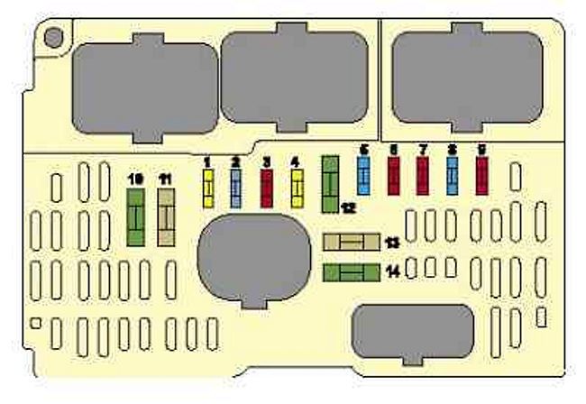
Main fuse box
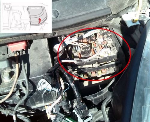
The main distribution box is located on the right side of the underhood. Remove the protective plastic cover to access it.
| Diagram | ||
|---|---|---|
|
||
| No. | Decoding | A |
| 1 | Cooling fan motor control module (low speed), engine management system | 20 |
| 2 | Horn (beep) | 15 |
| 3 | Windscreen / rear window washer pump | 10 |
| 4 | Headlight washers | 20 |
| 5 | Engine management | 15 |
| Fuel (Gasoline) pump fuse | ||
| 6 | Automatic transmission control system, cooling fan motor control unit (high speed) | 10 |
| 7 | ABS electronic control module, power steering system | 10 |
| 8 | Multifunctional control unit 2 | 20 |
| Starter | ||
| 9 | Multifunctional control unit 1 | 10 |
| Additional heating unit (diesel) | ||
| Fluid level sensor | ||
| 10 | Ignition system, petrol | 10 |
| Turbocharger valve | ||
| Engine management | ||
| Oxygen sensor in front of and behind the catalytic converter | ||
| Inlet air control valve (IACV) | ||
| Diesel contamination sensor | ||
| Fuel pressure regulator | ||
| MAP-controlled engine cooling thermostat | ||
| Variable timing of gas distribution | ||
| Exhaust gas recirculation valve | ||
| Injection pump, diesel | ||
| Coolant valve | ||
| Injectors | ||
| Variable air intake | ||
| Mass flow meter | ||
| 11 | Heater / air conditioner | 40 |
| 12 | Windshield wiper | 30 |
| 13 | Fuse / relay box, instrument cluster 1 | 40 |
| 14 | Exhaust air pump | 30 |
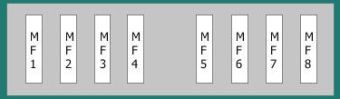
Maxi type fuses are installed at the bottom of the unit
|
||
|
||
| MF1 | Cooling Fan Motor Control Module | 50 |
| MF2 | Anti-lock braking system (ABS) | 30 |
| MF3 | 30 | |
| MF4 | Multifunctional control unit 1 | 80 |
| MF5 | 50 | |
| MF6 | Cabin fuse block | 50 |
| MF7 | - | |
| MF8 | Power steering | 70 |
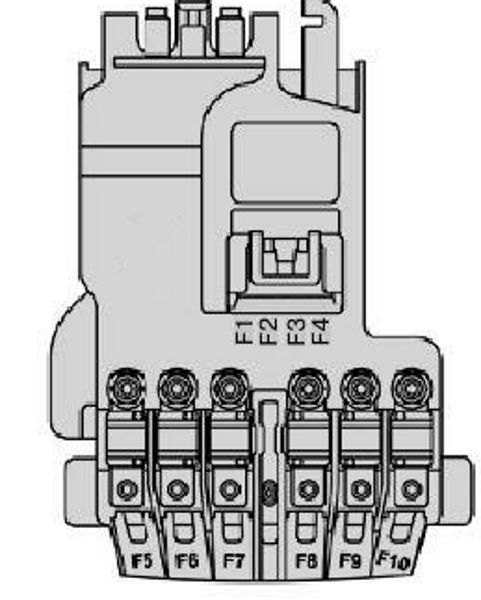
Power fuses
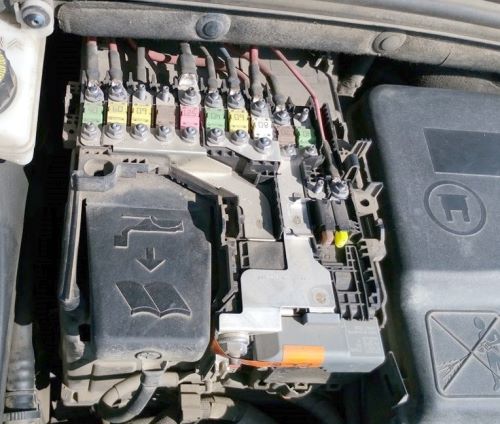
There is a board of high power fusible links on the battery.
| Diagram | ||
|---|---|---|
|
||
| No. | Description | A |
| F1 | Empty | - |
| F2 | Transmission (electronically controlled manual or automatic transmission) | 30 |
| F3 | Empty | - |
| F4 | Empty | - |
| F5 | Power steering pump | 80 |
| F6 | Heating unit (diesel engine) | 70 |
| F7 | Protection and switching unit | 100 |
| F8 | Empty | - |
| F9 | Electronically controlled manual transmission electric pump assembly | 30 |
| F10 | Valvetronic electric motor | 30 |
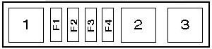
Auxilary fuse panel
On diesel engine models, an additional unit is located on the right side of the engine compartment.
| Diagram | ||
|---|---|---|
|
||
| No. | Decoding | A |
| F1 | Heater / air conditioner | 40 |
| F2 | 40 | |
| F3 | 40 | |
| F4 | Glow plug control unit | 80 |
| 1 | Auxiliary heater relay 1/2/3 | - |
| 2 | - | |
| 3 | - | |

Good