Citroen C5, a representative of the European D-class, was presented at the Paris Motor Show in 2000. Production of this model, which replaced the Xantia on the conveyor belt, began in 2001. It is equipped with a mode hydropneumatic suspension Hydractive III, as well as a wide list of electronic systems, combined with a multiplex bus. In this article, we will take a detailed look at the fuse box diagrams for the Citroen C5 X40 (1st generation; in sedan DC/RC and station wagon DE/RE bodies) 2001, 2002, 2003, 2004, 2005, 2006, 2007, 2008 years of manufacture.
Here you will find the locations and photos of distribution boxes. The fuses responsible for the “Cigarette lighter” and “Fuel Pump” are highlighted in bold.
In the engine compartment
There are two distribution boxes here that are responsible for protecting the electrical circuits.
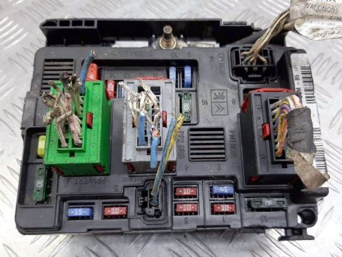
Main fuse box
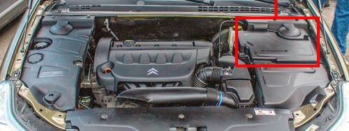
It is located on the right side of the underhood, next to the battery.
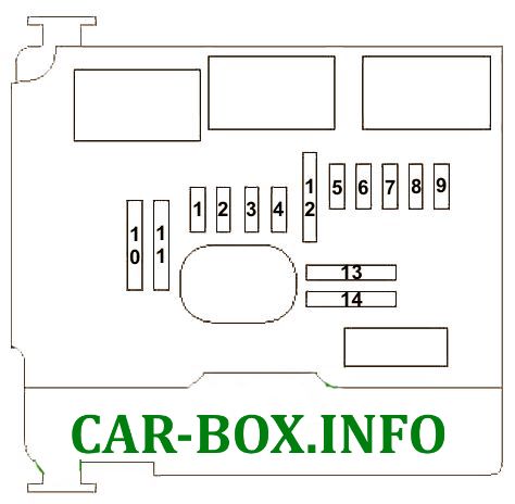
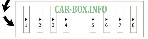
RE / RC bodies; 2004-2008 release
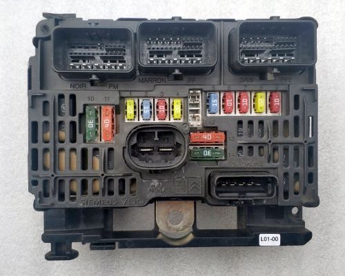
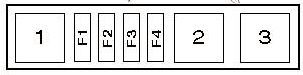
General view of the distribution box.
| Diagram | ||
|---|---|---|
|
||
| No. | Decoding | A |
| 1 | Cooling fan motor relay (low speed), engine control system | 20 |
| 2 | Horn (beep) | 15 |
| 3 | Windshield washers, rear window washer pump | 10 |
| 4 | Headlight washers | 20 |
| 5 | fuel pump fuse | 15 |
| 6 | Electronic control unit ABS, additional heater -Diesel | 10 |
| 7 | Automatic transmission control system, power steering | 10 |
| 8 | Starter | 20 |
| 9 | Stop lamp switch (brake pedal position sensor) | 10 |
| 10 | Engine management system, fuel heater - Diesel | 30 |
| 11 | Heater / air conditioner | 40 |
| 12 | Windshield wiper | 30 |
| 13 | Multifunctional control unit 1 | 40 |
| 14 | Exhaust air pump | 30 |
| Add. side board | ||
|
||
| F1 | Cooling fan motor control unit | 50 |
| F2 | Anti-lock braking system (ABS) | 30 |
| F3 | 30 | |
| F4 | Multifunctional control unit 1 | 80 |
| F5 | 80 | |
| F6 | Fuse / relay box, passenger compartment | 80 |
| F7 | Power steering | 70 |
| F8 | Suspension control actuator electric motor | 40 |
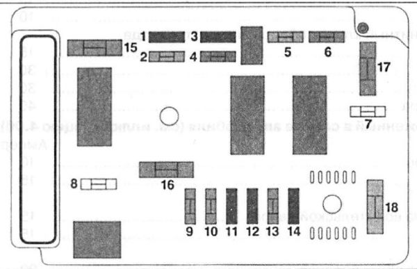
DE / DC body; 2001-2004
General view.
| Diagram | ||
|---|---|---|
|
||
| No. | Appointment | Amps |
| 1 | reversing lights | 10 |
| 2 | fuel (gasoline) pump | 30 |
| 3 | ignition, ABS control unit, suspension hydraulics unit | 10 |
| 4 | ignition, engine control unit, automatic transmission control unit | 7.5 |
| 5 | air cleaner sensor (diesel engines) | 2 |
| 6 | rear fog lights | 15 |
| 7 | headlight washers | 20 |
| 8 | fuel pump relay | 20 |
| 9 | left dipped beam | 15 |
| 10 | right dipped beam | 15 |
| 11 | left headlight high beam | 10 |
| 12 | right high beam headlamp | 10 |
| 13 | horn / beep | 15 |
| 14 | windscreen washer pump | 10 |
| 15 | ignition coil, idle speed solenoid valve, lambda probe | 15 |
| 16 | air pump | 30 |
| 17 | windshield wiper | 30 |
| 18 | air conditioner fan | 40 |
| Side add. panel | ||
|
||
| F1 | Cooling fan motor, cooling fan motor resistor, cooling fan motor relay - low speed, cooling fan motor relay - high speed | 50 |
| F2 | Anti-lock braking system (ABS) | 50 |
| F3 | ||
| F4 | Multifunctional control unit 1 | 80 |
| F5 | 80 | |
| F6 | Fuse box 2 (instrument panel) | 80 |
| F7 | Ignition lock | 30 |
| F8 | Suspension control system | 40 |
Additional fuse panel
Located near the right headlight
| Diagram | ||
|---|---|---|
|
||
| No. | Appointment | A |
| F1 | Coolant heater | 40 |
| F2 | 40 | |
| F3 | 40 | |
| F4 | Empty | - |
| 1 | Coolant Heater 1/2/3 Relay | - |
| 2 | - | |
| 3 | - | |
In the passenger compartment
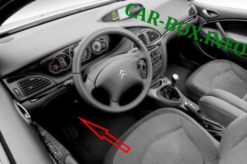
Located on the driver's side at the bottom of the dashboard.
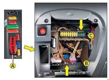
Access example. Two variations of the unit are possible in pre-styled models.
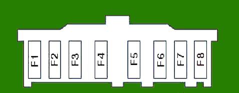
RE / RC bodies; 2004-2008 release
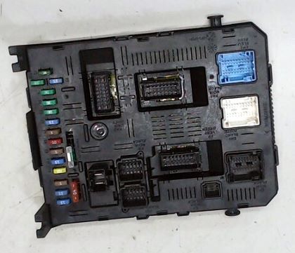
General view of the Citroen C5 interior fuse box.
| Diagram | ||
|---|---|---|

|
||
| No. | Appointment | A |
| 1 | Rear window wiper | 15 |
| 2 | central locking system | 30 |
| 3 | SRS electronic control unit | 5 |
| 4 | Auto-dimming interior mirror, brake light switch (brake pedal position sensor), diagnostic connector, stability control, automatic headlight corrector | 10 |
| 5 | Front power windows, sunroof | 30 |
| 6 | Power windows - rear | 30 |
| 7 | Interior lamps | 5 |
| 8 | Tire pressure monitoring system | 20 |
| 9 | Accessory connection socket, cigarette lighter socket | 30 |
| 10 | Active suspension system, multifunction switch on steering wheel, multifunction display, audio system | 20 |
| 11 | Ignition lock, automatic transmission control system | 15 |
| 12 | Unbuckled seatbelt indicator, lane marking system, rain sensor (windshield wiper system), sunshine sensor (air conditioning system) | 15 |
| 13 | Multifunction control unit 1, trailer control unit | 5 |
| 14 | Air conditioning system, instrument cluster, SRS, parking system | 15 |
| 15 | Central locking, instrument cluster | 30 |
| 17 | Rear window heater | 40 |
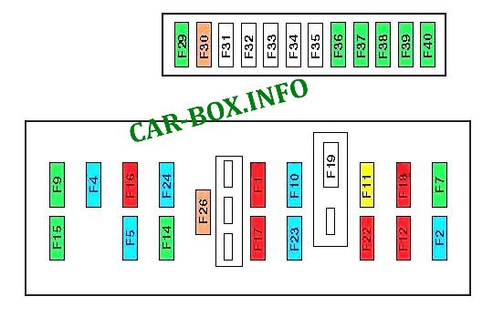
Type 1 (DE / DC bodies; 2001-2004)
Assignment of the fuses in the passenger compartment.
| Diagram | ||
|---|---|---|
|
||
| No. | Description | A |
| F1 | Rear fog lights | 10 |
| F2 | Rear window wiper motor | 15 |
| F4 | Driver-side door electrical control unit, passenger-side door electrical control unit, power seat drive, electric sunroof drive motor | 15 |
| F5 | Left brake light, brake light (upper) | 15 |
| F7 | Roof console, interior lighting bulb - rear, duffel box illumination bulb, air conditioning/heater control panel, cigarette lighter fuse C5, accessory connector - front | 20 |
| F9 | Driver-side door electrical control unit, passenger-side door electrical control unit, sunroof actuator motor | 30 |
| F10 | Additive nozzle, trailer electrical connector | 15 |
| F11 | Electronic engine control unit (RLZ), electronic transmission control unit, gear engaged sensor, steering column electrical control unit, audio system, navigation system control unit, air conditioning/heater control panel, multifunction display, anti-theft alarm system buzzer. | 15 |
| F12 | Automatic transmission mode sensor, front right parking light bulb, rear right parking light bulb, license plate illumination lamps, cigarette lighter, audio system | 10 |
| F14 | Door electrical control unit - driver's side, door electrical control unit - passenger's side, central locking - first, electric hatch / fuel filler flap drive | 30 |
| F15 | Central locking - rear, power rear windows | 30 |
| F16 | Fuse box 1 (engine compartment), additive control unit, steering column electrical control unit, SRS electronic control unit | 5 |
| F17 | Right brake light | 10 |
| F18 | Cruise control system, automatic transmission control system, diagnostic connector, steering column electrical control unit | 10 |
| F19 | - | - |
| F22 | Front left-hand side, rear left-hand side | 10 |
| F23 | Suspension control system | 15 |
| F24 | Instrument cluster, multifunctional digital display, air conditioning/heater control panel, parking system control unit | 15 |
| F26 | - | |
| F36 | Audio system output amplifier | 30 |
| F37 | Power Seat - Passenger Side | 30 |
| F38 | Power Seat - Driver Side | 30 |
| F39 | Passenger seat heater | 30 |
| F40 | Driver seat heater | 30 |
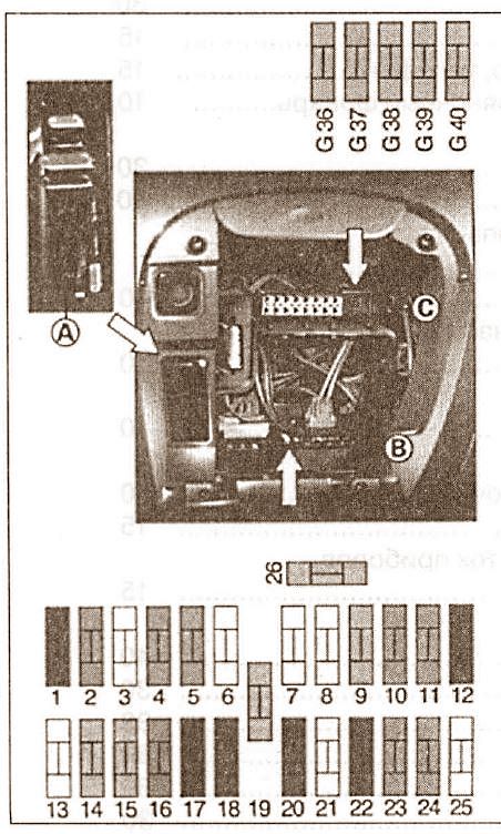
Type 2 (DE / DC bodies; 2001-2004)
Assignment of the fuses in the passenger compartment.
| Diagram | ||
|---|---|---|
|
||
| No. | Appointment | A |
| 1 | rear fog light | 10 |
| 2 | rear window wiper | 15 |
| 3 | - | - |
| 4 | alarm sensor on the driver's door | 15 |
| 5 | rear left brake light | 15 |
| 6 | - | - |
| 7 | equipment positive circuit | 20 |
| 8 | - | - |
| 9 | front power windows, sunroof | 30 |
| 10 | positive circuit terminal | 15 |
| 11 | security alarm display, navigator, air conditioning, telephone | 15 |
| 12 | front right parking light, rear right parking light | 10 |
| 13 | - | - |
| 14 | central locking system | 30 |
| 15 | rear power window | 30 |
| 16 | paddle switches, airbag control unit, fuse box in the engine compartment | 5 |
| 17 | right brake light | 10 |
| 18 | steering wheel position sensor, automatic transmission lever position sensor, diagnostic connector | 10 |
| 19 | - | - |
| 20 | navigator, radio | 10 |
| 21 | - | - |
| 22 | front left parking light, rear left parking light | 10 |
| 23 | suspension hydraulics unit, ABS control units | 15 |
| 24 | air conditioning, telephone, parking aid system, instrument panel, telephone signal amplifier | 15 |
| 25 | - | - |
| 26 | rear window heater | 40 |
| G36 | radio amplifier | 30 |
| G37 | power front right seat | 30 |
| G38 | power front left seat | 30 |
| G39 | front right seat heater | 30 |
| G40 | front left seat heater | 30 |
