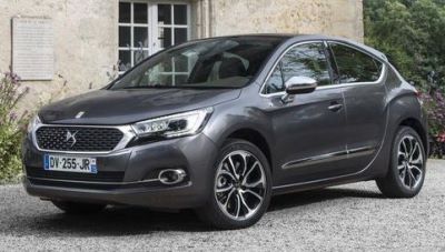
The DS4 hatchback is the second car created by Citroen under the new premium DS brand and was presented in 2011. The model is based on the second-generation C4, but has a lot of differences from its donor. Increased ground clearance relates it to compact urban crossovers. In this article, we will take a detailed look at the fuse box diagrams for the Citroen DS4 (body N) 2011. 2012, 2013, 2013, 2014, 2015, 2015, 2016, 2016, 2017, 2018, 2018, 2019, 2020 and 2021 years of manufacture.
Here you will find the locations and photos of distribution boxes. The fuses responsible for the “Cigarette lighter” and “Fuel Pump” are highlighted in bold.
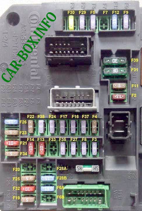
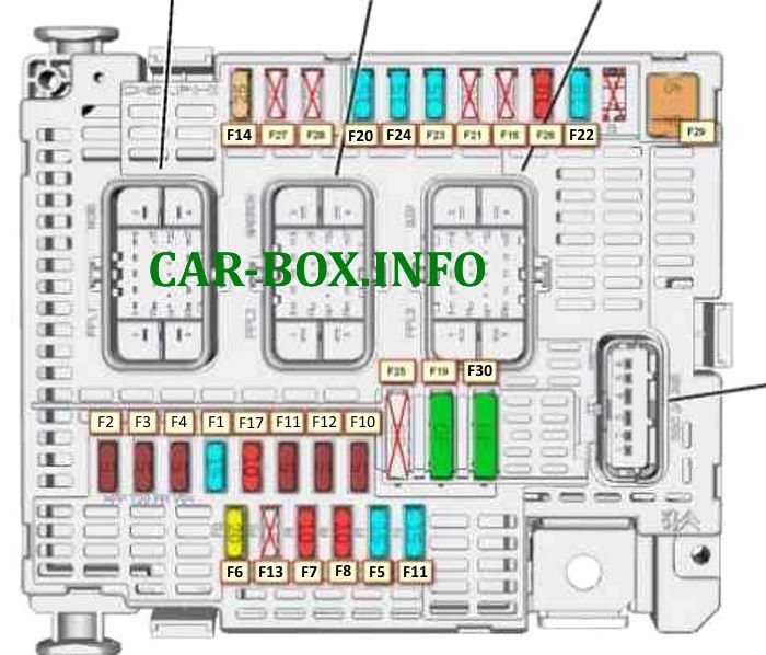
In the passenger compartment
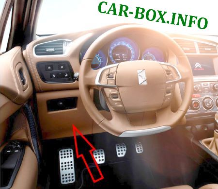
Located on the driver's side, at the bottom of the dashboard.
Example of access.
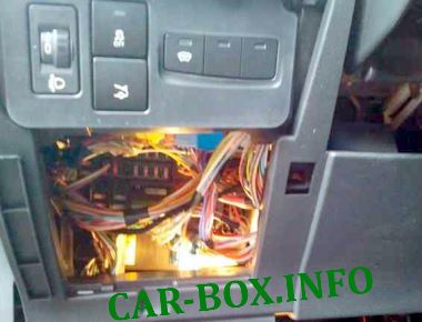
General view of the Citroen DS4 interior fuse box.
| Diagram | ||
|---|---|---|
|
||
| No. | Decoding | A |
| F2 | 7.5 | |
| F3 | Anti-theft device or "START/STOP" button. | 3 |
| F4 | Remote key reader. | 5 |
| F5 | Remote control key. | 3 |
| F6A / B | Car radio | 15 |
| F7 | Electronic unit of the hands-free start assist system | 15 |
| F8 | Security alarm siren, security alarm processor. | 3 |
| F9 | The switch box on the steering wheel. | 3 |
| F11 | Stability control calculator | 5 |
| F12 | 15 | |
| F13 | Front cigarette lighter fuse | 10 |
| F14 | Rear cigarette lighter | 10 |
| F16 | Rear individual lights, illuminated glove box. | 3 |
| F17 | Sun visor illumination, front individual lights. | 3 |
| F19 | Dashboard. | 5 |
| F21 | Controls the car radio and climate control system. | 10 |
| F22 | Displays, parking sensors. | 5 |
| F23 | Engine compartment fuse module | 5 |
| F24 | Rain and light sensor | 3 |
| F25 | Airbag and pyrotechnic tensioner unit | 15 |
| F26 | - | 15 |
| F27 | Dual brake pedal contactor | 3 |
| F28A / B | Car radio, autoradio (extra equipment). | 15 |
| F29 | - | 3 |
| F30 | - | 20 |
| F31 | Central locking system | 30 |
| F32 | Power supply for rear view camera in C4L China. (16V NE 13pin output) | 10 |
| F34 | - | 5 |
| F35 | - | 3 |
| F37 | Driver's door wiper/mirror control - electrochromed interior rearview mirror | 3 |
| F38 | - | 3 |
| F39 | - | 10 |
| Additional board BFH3 located next to the main unit | ||
|
||
| F1 | rear window heating | 40 |
| F2 | heated mirrors | 7.5 |
| F3 | relay | 10 |
| F5 | rear power window | 30 |
| F6 | front power windows | 30 |
| F7 | electrically adjustable driver's seat | 30 |
| F8 | Sunroof | 30 |
| R1 | exterior mirrors | |
| R2 | rearview mirror folding | |
| R3 | heated rear window / heated mirrors | |
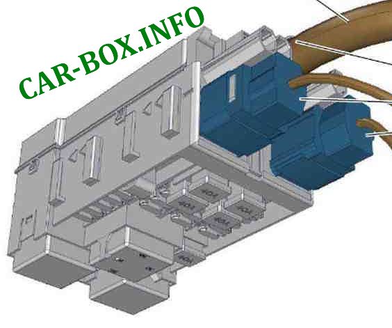
In the engine compartment
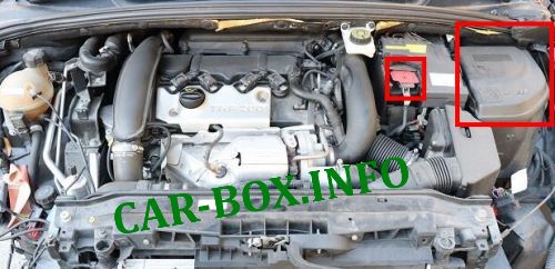
There are two units here: the main unit near the battery, and the power board on its plus terminal.
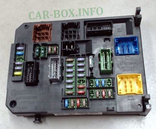
Main fuse box
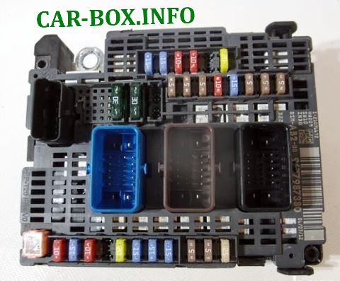
General view.
| Diagram | ||
|---|---|---|
|
||
| No. | Description | A |
| F1 | power supply protection and distribution unit | 15 |
| F2 | fan group control unit | 5 |
| F3 | engine control | 5 |
| F4 | 15 | |
| F6 | fuel pump with fuel gauge | 20 |
| F7 | Engine management | 10 |
| F8 | 10 | |
| F10 | Cruise control safety contactor - automatic transmission computer | 5 |
| F11 | Left headlight - right headlight - ionizer | 15 |
| F14 | Air conditioning compressor | 25 |
| F15 | Power steering electric pump mechanism | 5 |
| F17 | Inner rear view mirror with electrochromic coating - driver's door window/exterior mirror control board | 10 |
| F19 | Low / high speed of windscreen wiper operation | 30 |
| F20 | Windshield washer pump | 15 |
| F21 | Headlight washer pump | 20 |
| F22 | Horn (beep) | 15 |
| F23 | Right headlight | 15 |
| F24 | Left headlight | 15 |
| F26 | Air conditioning compressor | 10 |
| F29 | Starter | 30 |
| The individual fuses are located at the bottom of the unit: | ||
| F10 | Automatic transmission control group | 5 |
| F11 | Shift-lock relay | 5 |
| F12 | Automatic transmission computer | 15 |
Power fuse panel
Located on the battery.
| Diagram | ||
|---|---|---|

|
||
| No. | Decoding | A |
| F1 | Reserve | - |
| F2 | Transmission (electronically controlled manual or automatic transmission) | 30 |
| F3 | Reserve | - |
| F4 | Reserve | - |
| F5 | Power steering pump | 80 |
| F6 | Heating unit (diesel engine) | 70 |
| F7 | Protection and switching unit | 100 |
| F8 | Spare | - |
| F9 | Electronically controlled manual transmission electric pump assembly | 30 |
| F10 | Valvetronic electric motor | 30 |
