The first generation of Citroën Jumpy cars has been in serial production since 1995 at the new joint SEVEL plant in the south of France together with identical models Peugeot Expert and Fiat Scudo. In this article, we will take a detailed look at the fuse box diagrams for the Citroën Jumpy (1st generation) 1995, 1996, 1997, 1998, 1999, 2000, 2001, 2002, 2003, 2004, 2005, 2006, 2007 years of manufacture.

Here you will find the locations and photos of distribution boxes. The fuses responsible for the “Cigarette lighter” and “Fuel Pump” are highlighted in bold.
In the passenger compartment
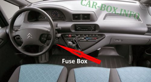
It is located under the dashboard on the driver's side or behind the glove box (right-hand drive).
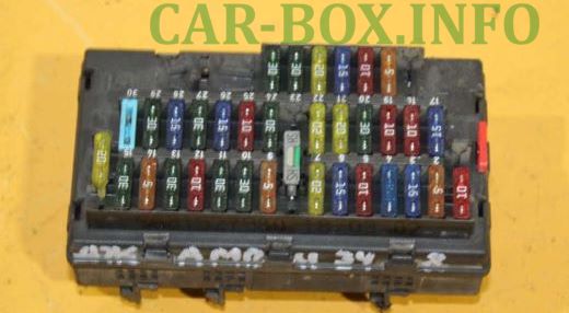
General view of the Citroen Jumpy interior fuse box.
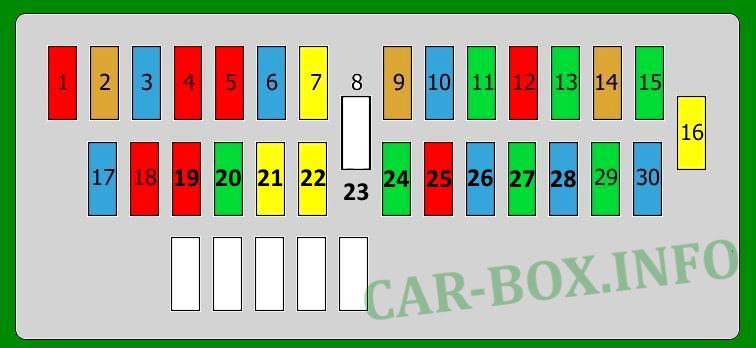
| Diagram | ||
|---|---|---|
|
||
| No. | Decoding | A |
| 1 | Audio system | 10 |
| 2 | Ignition + position | 5 |
| Speed sensor | ||
| CPH | ||
| Dashboard warning lamp (s) | ||
| 3 | Stop lights | 15 |
| Cruise control | ||
| 4 | Right side light | 10 |
| Left tail light | ||
| Headlight adjustment | ||
| 5 | Air conditioning | 10 |
| Front power windows | ||
| blower | ||
| Pressure switch | ||
| 6 | Heated rear windshield | 15 |
| Heated seats | ||
| 7 | Warning system | 20 |
| 8 | Shunt | |
| 9 | Right side light | 5 |
| Left tail light | ||
| License plate illumination lamp | ||
| Headlight washers | ||
| 10 | Front fog lights | 15 |
| 11 | Reserve | 30 |
| 12 | Back-up lamp | 10 |
| Diagnostic connector | ||
| 13 | Reserve | 30 |
| 14 | CPH | 5 |
| 15 | CPH | 30 |
| central locking system | ||
| Interior lighting | ||
| 16 | Citroen Jumpy cigarette lighter fuse | 20 |
| 17 | Coolant temperature control unit | 15 |
| Fan | ||
| 18 | Fog lights | 10 |
| 19 | Instrument lighting | 10 |
| Audio system | ||
| on-board lights | ||
| 20 | Air conditioning | 30 |
| 21 | Heated seats | 20 |
| 22 | Accessories + position | 20 |
| Reserve | ||
| 23 | Shunt | |
| 24 | Windshield washer | 30 |
| Windscreen wipers | ||
| 25 | Air conditioning | 10 |
| Interior lighting | ||
| Radio memory | ||
| Clock | ||
| 26 | Hazard warning lights | 15 |
| 27 | Rear window heating | 30 |
| 28 | Power windows | 15 |
| Charging indicator | ||
| 29 | Power windows | 30 |
| 30 | Interior lighting | 15 |
| Direction indicators | ||
| Clock | ||
| Electric rearview mirror | ||
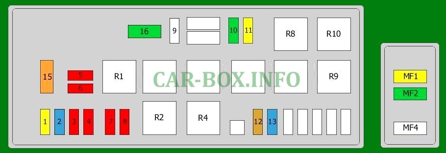
In the engine compartment
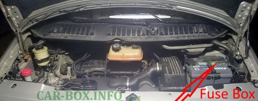
Fuse box located near the battery.
| Diagram (right hand drive) | ||
|---|---|---|
| No. | Description | A |
| ABS models | ||
|
||
| 1 | trailer | 20 |
| 2 | Fuel pump fuse | 15 |
| 2a | 20 | |
| 3 | Left dipped beam | 10 |
| 4 | Right dipped beam | 10 |
| 5 | Diagnostic connector | 10 |
| 6 | Electronic injection / Electronic anti-theft device | 10 |
| 7 | Left high beam | 10 |
| 8 | Right high beam | 10 |
| 9 | Engine cooling fan | 25 |
| 9a | Engine cooling fan | 40 |
| 10 | Headlight washers | 30 |
| 11 | Additional heater | 2 |
| 12 | Headlight washer pump | 5 |
| 13 | Catalytic converter sensor | 15 |
| 14 | ||
| 15 | Air conditioning | 40 |
| 16 | Engine cooling fan | 30 |
| 16a | 50 | |
| MF1 | 20 | |
| MF2 | Injection relay | 30 |
| MF4 | ABS control unit | 60 |
| R1-R10 | Unknown | |
| Cars without ABS | ||

|
||
| 1 | Fuel (Gasoline) pump fuse | 20 |
| 2 | Right dipped beam | 10 |
| 3 | Left dipped beam | 10 |
| 4 | Headlight washers | 25 |
| 5 | Shunt | - |
| 6 | Electronic anti-theft device | 10 |
| 7 | Catalytic converter sensor | 10 |
| 8 | trailer | 20 |
| 9 | Fan | 25 |
| 9a | 30 | |
| 10 | Reserve | 15 |
| 11 | Reserve | 5 |
| 12 | Left high beam | 10 |
| 13 | Right high beam | 10 |
| MF1 | Spare | 20 |
| MF2 | Spare | 30 |
| Description of relays and fuses in the engine compartment (left hand drive) | ||
|---|---|---|

General view of the distribution box. |
||
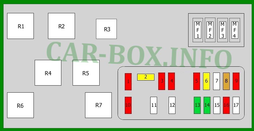
diagram. |
||
| No. | Decoding | A |
| 1 | Left high beam | 10 |
| 2 | Fuel pump | 20 |
| 3 | Spare | 10 |
| 4 | Left low beam | 10 |
| 5 | Right low beam | 10 |
| 6 | Spare | 20 |
| 7 | Empty | |
| 8 | Spare | 5 |
| 9 | Fuel pump relay | 10 |
| Additional relay, fuel pump | ||
| 10 | Right high beam | 10 |
| 11 | Empty | |
| 12 | Headlight washers | 25 |
| 13 | Fan | 30 |
| 14 | Spare | 30 |
| 15 | Empty | - |
| 16 | Spare | 10 |
| 17 | Diagnostic connector | - |
| Trailer connector | - | |
| MF1 | Main light switch | 70 |
| Main relay | ||
| Passenger compartment fuse box | ||
| MF2 | Passenger compartment fuse box | 70 |
| Ignition switch | ||
| ADC panel (anti-start system) | ||
| Main relay | ||
| MF3 | Secondary air pump relay | 40 |
| MF4 | Fan | 50 |
| R1 | Air conditioning | - |
| R2 | Fan | - |
| R3 | Empty | - |
| R4 | Headlight washers | - |
| R5 | Fan | - |
| R6 | Air conditioning | - |
| R7 | Fan | - |
