The second generation Citroen Jumpy saw the light of day in 2006, but the model reached the Russian market only in the second half of 2013, after a small facelift, mainly affecting the design of the front end. In this article, we will take a detailed look at the fuse box diagrams for the Citroen Jumpy (2Gen) 2007, 2008, 2009, 2010, 2011, 2012, 2013, 2013, 2014, 2015, 2016, 2017 years of manufacture.
Here you will find the locations and photos of distribution boxes. The fuses responsible for the “Cigarette lighter” and “Fuel Pump” are highlighted in bold.
In the passenger compartment
There is one main unit here, and three additional units.
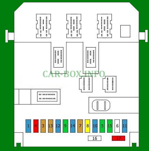
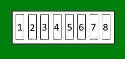
Main fuse box
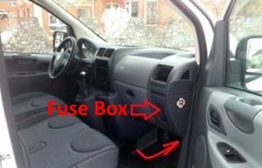
Located behind the glove box. To access, lower the glove box and pull it forcefully.
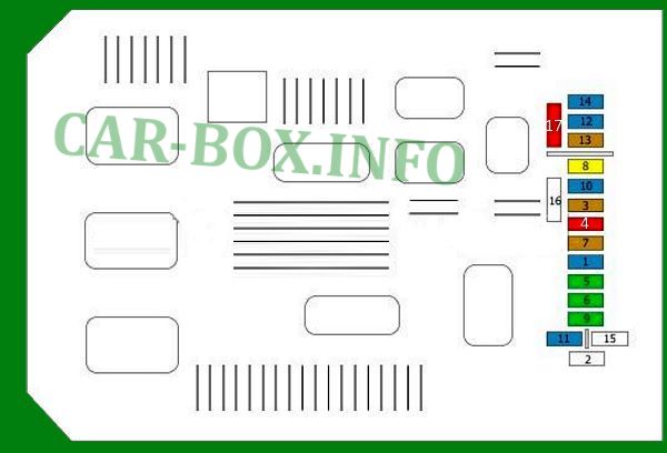
Type 1
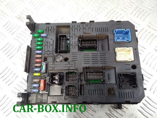
General view.
| Diagram | ||
|---|---|---|
|
||
| No. | Description | A |
| 1 | Rear wiper | 15 |
| 2 | Reserve | |
| 3 | Airbag control unit | 5 |
| 4 |
|
10 |
| 5 |
|
30 |
| 6 | Front power windows | 30 |
| 7 | Interior lighting | 5 |
| 8 |
|
2 |
| 9 |
|
30 |
| 10 | Height sensor, Steering wheel controls, Instrument panel | 15 |
| 11 | Diagnostic connector, Ignition switch | 15 |
| 12 | Handsfree kit, Airbags, Parking assistance system | 15 |
| 13 | Fuse box in the engine compartment, Trailer control module | 5 |
| 14 | Rain sensor, Air conditioning, Dashboard | 15 |
| 15 | Unknown | - |
| 16 | Unknown | - |
| 17 | Rear window heating | 10 |
Type 2

General view of the Citroen Jumpy interior fuse box.
| Diagram | ||
|---|---|---|
|
||
| No. | Decoding | A |
| 1 | Rear wiper motor | 15 |
| 3 | Airbag control module | 5 |
| 4 |
|
10 |
| 5 | Power window on driver's side, Electric mirror control, Front passenger side power window switch | 30 |
| 6 | Empty | - |
| 7 | Glove compartment light switch, Front left lamp, Rear interior light, Front right lamp, Audio system | 5 |
| 8 | Alarm control unit, Audio system, Radio phone, Alarm siren, Trailer fuse box | 20 |
| 9 |
|
30 |
| 10 |
|
15 |
| 11 | Diagnostic connector / Ignition switch | 15 |
| 12 |
|
15 |
| 13 |
|
5 |
| 14 |
|
15 |
| 15 | Tailgate / Trunk Release Relay | 30 |
| 17 | Heated rear windshield Electric mirrors Rear window heater, left side Heated rear window, right side |
10 |
| 16 | Shunt | |
Auxilary fuse panels
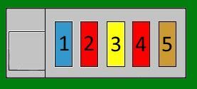
Panel #1 located next to the main unit.
| Diagram | ||
|---|---|---|

|
||
| 1 | Heated front seats | 30 |
| 2 | Rear 12V power outlet | 20 |
| 3 | Trailer fuse box | 40/50 |
| 4 | - | |
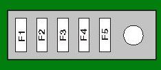
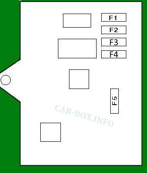
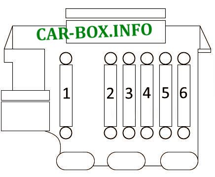
Panel #2 located in the front passenger footwell.
| Diagram | ||
|---|---|---|
|
||
| No. | Description | A |
| F1 | central locking system | 15 |
| F2 | central locking system | 10 |
| F3 | Rear window wiper | 20 |
| F4 | 10 | |
| F5 | Folding rear view mirrors on the doors | 5 |
Panel #3 located behind the glove box.
| Diagram | ||
|---|---|---|
|
||
| 1 | Tailgate / Trunk Release Relay | 15 |
| 2 | 10 | |
| 3 | Rear wiper relay | 20 |
| 4 | Coolant pump relay | 10 |
| 5 | Rearview mirror | 5 |
In the luggage compartment
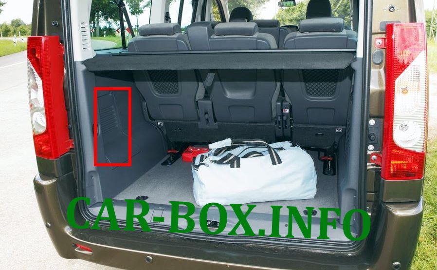
It is located behind the trim on the left side.
| Diagram | ||
|---|---|---|
|
||
| No. | Description | A |
| F1 | 3 | |
| F2 | Ignition | 15 |
| F3 | Trailer electrical equipment | 15 |
| F4 | 15 | |
| F5 | Alarm | 40 |
In the engine compartment
Fuse box
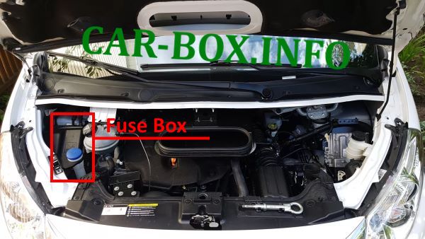
It is located on the left side of the underhood, in some modifications it can be placed on the right side and have a different design. In addition, the battery is equipped with a board of high-power fusible links.
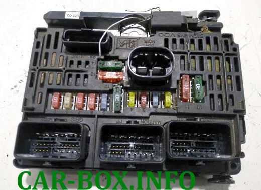
Type 1
Assigment of the fuses.
| Diagram | ||
|---|---|---|

|
||
| No. | Decoding | A |
| 1 | Main relay | 20 |
| 2 | Signal | 15 |
| 3 | Front and rear windscreen washers | 10 |
| 4 | Headlight washer pump | 20 |
| 5 |
|
15 |
| 6 |
|
10 |
| 7 | ABS / ESP control unit | 10 |
| 8 | Starter solenoid | 20 |
| 9 | Brake pedal switch | 10 |
| 10 |
|
30 |
| 11 | Heating and air conditioning | 40 |
| 12 | Front wiper control | 30 |
| 13 | at BSI (Intelligent Power Distribution Module) | 40 |
| 14 | Not | 30 |
| 15 | Right high beam | 10 |
| 16 | Left high beam | 10 |
| 17 | Left dipped beam | 15 |
| 18 | Right dipped beam | 15 |
| 19 |
|
15 |
| 20 |
|
10 |
| 21 |
|
5 |
| MF1 | Not | |
| MF2 | ABS / ESP control unit | 40 |
| MF3 | 30 | |
| MF4 | at BSI (Intelligent Power Distribution Module) | 60 |
| MF5 | 70 | |
| MF6 | Additional heater | 20 |
| MF7 | Automatic transmission control unit | 20 |
| MF8 | Fan relay | 30 |
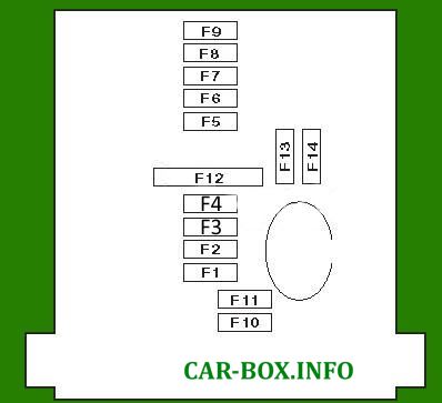
Type 2
General view.
| Diagram | ||
|---|---|---|
|
||
| No. | Appointment | A |
| F1 | Engine Control Unit, Fuel and Air Supply Systems, | 20 |
| Fan assembly | ||
| F2 | Horn (beep) | 15 |
| F3 | Front and rear windscreen washer pump | 10 |
| F4 | Headlight washers | 20 |
| F5 | Gasoline : Engine management | 15 |
| F6 | Power steering, Additional brake pedal | 10 |
| F7 | Brake system ABS / ESP | 10 |
| F8 | Launch system | 20 |
| F9 | Brake pedal master switch | 10 |
| F10 | Engine management | 30 |
| F11 | Air conditioner / heater fan motor | 40 |
| F12 | Windshield wiper | 30 |
| F13 | Embedded systems interface | 40 |
| F14 | Reserve | 30 |
| Additional board located on the side | ||
|
||
| 1 | Air conditioner / heater fan motor | 30 |
| 2 | ABS / ESP system | 40 |
| 3 | 30 | |
| 4 | 60 | |
| 5 | 70 | |
| 6 | Additional heater | 20 |
| 7 | - | |
| 8 | 30 | |
Power fuse panel
Located on the battery.
| Diagram | ||
|---|---|---|
|
||
| No. | Description | A |
| 1 | Power steering pump | 100 |
| 2 | Cooling fan, fast relay | 60 |
| 3 | Cooling fan relay, left side | 60 |
| 4 | Suspension control unit | 40 |
| 5 | Heating control unit | 100 |
| 6 | - | |
