The Xsara was launched by Citroen in the fall of 1997, originally in a five-door hatchback body. The exterior was designed by Italian Donato Coco. The design of the hatchback turned out to be very expressive, thanks to the increased slope of the hood, graceful headlights and a stylish signature grille. In this article, we will take a detailed look at the fuse box diagrams for the Citroen Xsara (codename N) 1997, 1998, 1999, 2000, 2001, 2002, 2003, 2004, 2005, 2006 years of manufacture.

Here you will find the locations and photos of distribution boxes. The fuses responsible for the “Cigarette lighter” and “Fuel Pump” are highlighted in bold.
In the engine compartment
There are two distribution boxes here that are responsible for protecting the electrical circuits.
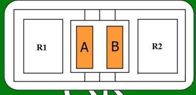
Fuse box
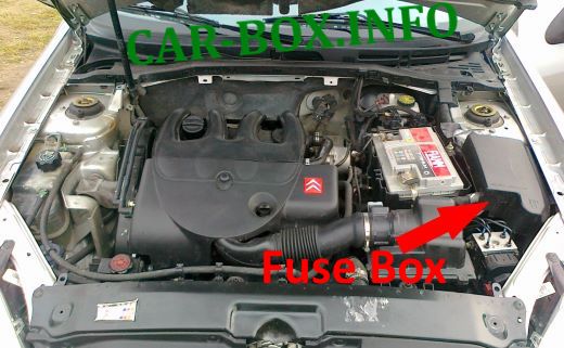
Located near the battery.
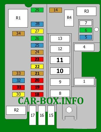
Models 2000-2006 release
General view.
| Diagram | ||
|---|---|---|
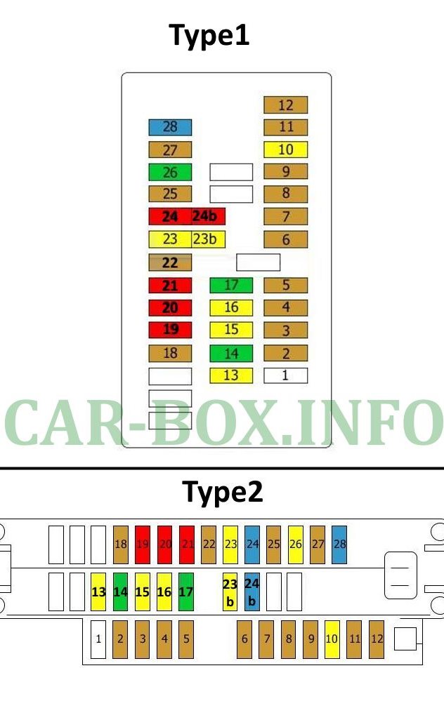
| Type 1 | ||
|
||
| No. | Decoding | A |
| MF1 | BSI | 50 |
| MF4 | Anti-lock braking system | 50 |
| MF8 | Fuse box No. 1 in the passenger compartment | 70 |
| MF9 | BSI | 50 |
| MF10 | Relay of auxiliary heater | 40 |
| MF11 | Fuse box No. 1 in the passenger compartment | 30 |
| MF12 | Ignition switch | 50 |
| MF13 | Not | 40 |
| MF15 | Fan | 50 |
| MF17 | Not used | 40 |
| 5 | Low beam relay | 15 |
| 6 | Not | 30 |
| 7 | Fuel heater | 25 |
| 14 | Alarm siren | 5 |
| 18 | High beam | 30 |
| 19 | 10 | |
| 20 | Stop signal | 10 |
| 21 | Not | 5 |
| 22 | BSI | 20 |
| 23 | Anti-lock braking system | 10 |
| 24 |
|
5 |
| 25 | Fuel pump fuse | 15 |
| 26 | Double relay | 30 |
| 27 |
|
20 |
| 28 |
|
15 |
| 29 |
|
30 |
| 30 |
|
20 |
| 31 | Not | 10 |
| 32 |
|
15 |
| 33 | Automatic transmission control unit | 5 |
| 34 | - | 5 |
| R1 | Air pump relay | |
| R2 | Rear fog lamps | |
| R3 | Headlight washer pump | |
| R4 | Diagnostic System / Automatic Transmission | |
| Type 2 | ||
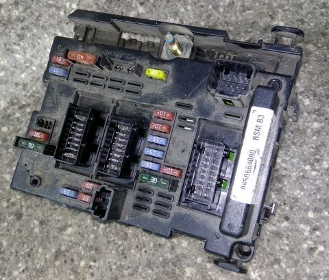
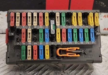
The photo shows an example. 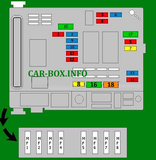
|
||
Type 3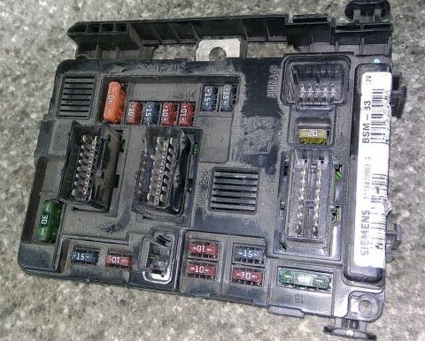
The photo shows an example. 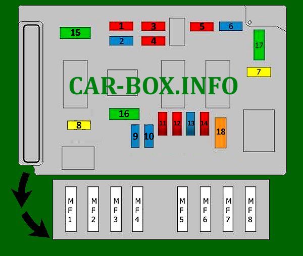
|
||
| No. | Description | A |
| 1 | Automatic transmission control system, cooling fan motor relay, reversing lights | 10 |
| 2 | Coolant heater, fuel pump | 15 |
| 3 | Anti-lock braking system (ABS) | 10 |
| 4 | Automatic transmission control system, engine management system | 10 |
| 5 | Anti-theft system horn - if installed, automatic transmission control system, engine control system | 10 |
| 6 | Fog lights | 15 |
| 7 | Headlight washer pump | 20 |
| 8 | Anti-lock braking system (ABS), cooling fan motor relay, engine management system | 20 |
| 9 | Left headlight - dipped beam | 15 |
| 10 | Right headlight - dipped beam | 15 |
| 11 | Left headlight - high beam | 10 |
| 12 | Right headlight - high beam | 10 |
| 13 | Horn | 15 |
| 14 | Rear window washer pump motor | 10 |
| 15 | Engine management | 30 |
| 16 | Exhaust air pump | 30 |
| 17 | Windshield wiper | 30 |
| 18 | Heater / air conditioner | 40 |
| MF1 | Cooling fan motor relay | 50 |
| MF2 | Anti-lock braking system (ABS) | 50 |
| MF3 | Coolant heater | 30 |
| MF4 | Multifunctional control unit 1 | 50 |
| MF5 | Anti-lock braking system (ABS) multifunction control unit 1 | 50 |
| MF6 | Passenger compartment fuse box | 30 |
| MF7 | Ignition lock | 50 |
| MF8 | Passenger compartment fuse box | 70 |
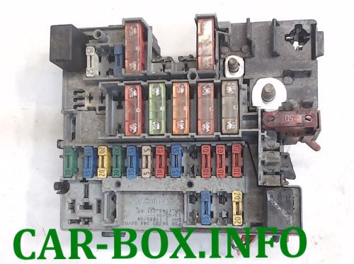
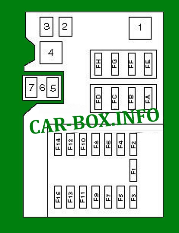
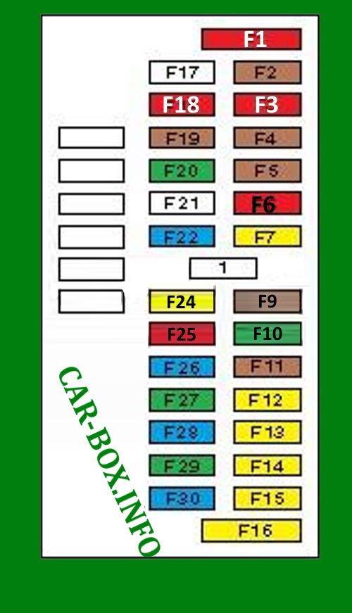
Models up to 2000 release
| Diagram | ||
|---|---|---|
|
||
| No. | Decoding | A |
| F1 | Headlight washers | 20 |
| F2 | - | |
| F3 | Cooling Fan Motor - 120W / 200W (1998 ^) | 20/30 |
| F4 | - | |
| F5 | Cooling Fan Motor - 120W / 200W (1998 ^) | 30 |
| F6 | Fog lamp relay | 20 |
| F7 | Cooling Fan Motor - A / C (^ 1997) | 5 |
| F8 | - | |
| F9 | Fuel pump fuse | 15 |
| F10 | Throttle Body Heater | 10 |
| F11 | Oxygen sensor heater | 15 |
| F12 | Left headlight - high beam | 10 |
| F13 | Right headlight - high beam | 10 |
| F14 | Left headlight - dipped beam | 10 |
| F15 | Right headlight - dipped beam | 10 |
| FA | Fuel system, ignition switch | 60 |
| FB | 40 | |
| FC | Fuel system, cabin distribution box | 80 |
| FD | Fuel system, light switch | 40 |
| FE | Fuel system, cooling fan motor | 40 |
| FF | 40 | |
| FG | - | |
| FH | Anti-lock braking system (ABS) | 50 |
| 1 | Fog lamp relay | |
| 2 | Air conditioner compressor solenoid clutch disconnect relay | |
| 3 | Air conditioner compressor solenoid clutch relay | |
| 4 | Headlight washer delay relay | |
| 5 | Fuel injection advance angle control valve e/m relay | |
| 6 | Starter relay - automatic transmission | |
| 7 | Power steering relay | |
Additional relay blocks
Located in the engine compartment.
| Diagram | |
|---|---|
| No. | Appointment |

|
|
| R1 | Front fog lamp relay |
| R2 | Compressor shutdown |
| R3 | A / C Compressor Relay / Horn |
| R4 | Headlight washer timer |
| R5 | Diesel pre-post heating |
| R6 | Pre-correction |
| R7 | Power steering / automatic transmission relay |
|
|
| A | 40A Coolant Heater |
| B | |
| R1 | Coolant heater relay |
| R2 | |
In the passenger compartment
There are two distribution boxes here that are responsible for protecting the electrical circuits.
Fuse box
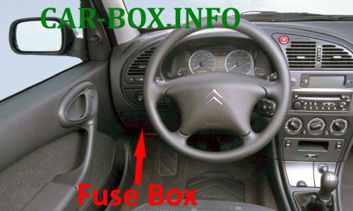
Located on the driver's side of the dashboard.
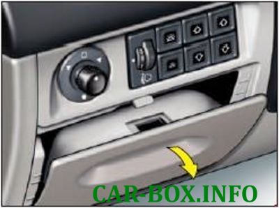
Access example.
From 2000 release
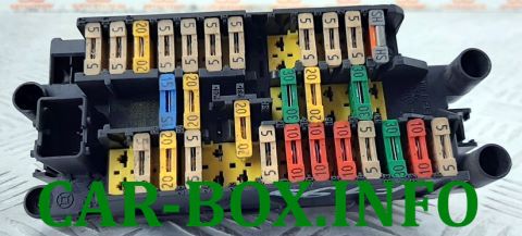
General view of the Citroen Xsara interior fuse box.
| Diagram | ||
|---|---|---|
|
||
| No. | Decoding | A |
| 1 | Jumper | |
| 2 | Jumper | |
| F2 | Air conditioning system | 5 |
| F3 | Diagnostic connector (DLC) instrument cluster | 5 |
| F4 | Multifunction control unit 1, ignition control | 5 |
| F5 | Automatic transmission | |
| F6 | Interior lamps | |
| F7 |
|
10/5 |
| F8 | Diagnostic connector, clock, multifunction display, alarm, steering column electrical control unit | 5 |
| F9 | Multifunctional control unit 1 | 5 |
| F10 | Radio, signal, special equipment / Navigation system, trailer electrical connector | 10 |
| F10 | Auto PC, Signal, Trailer Connector, Emergency Alarm, Headlight Washers, Special Equipment/Radio, Signal, Special Equipment, Security Alarm Relay, Headlight Washer Relay, Low Beams | 20 |
| F11 | Front left parking light, rear right parking light | 5 |
| F12 | Rear left light bulb, license plate light bulb, front right light bulb | 5 |
| F13 | Daytime running light system | 20 |
| F14 | Power windows - front | 30 |
| F15 | Seat heater | 20 |
| F16 | Sunroof | 20 |
| F17 | Battery / Multifunction control unit 1 | 15/30 |
| F18 | Lighting system, Steering wheel sensor, Clock, Heated rear windshield, Rear window lock, Security alarm system, Multifunction display, 12V outlet, Parking aid, Cigarette lighter, Automatic transmission lever, Air conditioning | 5 |
| F19 |
|
10 |
| F20 | Coolant heater, engine management system, fuel filter water sensor, vehicle speed sensor | 5 |
| Left dipped beam, Headlight adjustment | 10 | |
| F21 |
|
10 |
| F22 | Rain sensor / Interior lighting / Duffel box light bulb, interior lighting bulbs, local light bulbs, cosmetic mirror light bulb - passenger side | 5 |
| F23 | Accessory connector, Citroen Xsara cigarette lighter fuse | 20 |
| F24 | Audio system | 15 |
| F25 | Clock, interior mirror | 5 |
| F26 | Front and rear wiper switch | 20 |
| F27 | Multifunctional control unit 1 | 5 |
| F28 | Power Seat - Driver Side | 15 |
Up to 2000 release
General view.
| Diagram | ||
|---|---|---|
|
||
| No. | Description | A |
| 1 | Jumper | |
| F1 | Audio system, audio system CD changer | 10 |
| F2 | Transmission selector illumination lamp, cooling fan motor control unit, air conditioner control unit, sensor - air conditioning refrigerant pressure switch (triple), diagnostic connector, speed sensor, instrument cluster indicators, cooling fan motor relay - dual fan (left), cooling fan motor relay - dual fan (right), multifunction control unit | 5 |
| F3 | ABS electronic control unit | 10 |
| F4 | Rear right parking light, front left parking light | 5 |
| F5 | Daytime Lighting System (If Equipped) | 5 |
| F6 | Electronic transmission control unit | 10 |
| F7 | Horn, trailer electrical connector | 20 |
| F9 | Rear left parking light, front right parking light, license plate illumination lamps | 5 |
| F10 | Rear power windows | 30 |
| F11 | - | |
| F12 | Instrument cluster indicators, reversing lights, brake lights | 20 |
| F13 | Daytime Lighting System (If Equipped) | 20 |
| F14 | - | |
| F15 | Cooling fan motor control unit, multifunction control unit | 20 |
| F16 | Cigarette lighter fuse | 20 |
| F17 | - | |
| F18 | Rear fog lamp | 10 |
| F19 | Warning buzzer for lamps left on, front parking lamps | 5 |
| F20 | Air flow direction damper actuator motor (air conditioner/heater) | 30 |
| F21 | Door mirror heaters, seat heaters, rear window heater shut-off timer relay, air conditioning system | 25 |
| F22 | Power seat | 15 |
| F24 | Rear and windshield wiper / washer, windshield wiper motor, rain sensor | 20 |
| F25 | Audio system, clock, anti-theft system LED, instrument cluster, diagnostic connector, multifunction control unit | 10 |
| F26 | Alarm | 15 |
| F27 | Front power windows, sunroof | 30 |
| F28 | Power window lock switch, instrument cluster, turn signal relay, duffel box illumination lamp | 15 |
| F29 | Rear window heater switch-off timer relay, door mirror heaters | 30 |
| F30 | Rain sensor, spot lights, outside temperature sensor, rear window wiper motor, power windows, sunroof, power door mirrors, power door mirrors | 15 |
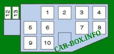
Relay box
Located above the pedals in the instrument panel, on the right side of the fuse box.
|
|
| 1 | |
| 2 | Rear Power Window Disconnect Relay |
| 3 | Indication relay |
| 4 | power window - rear |
| 5 | heater fan |
| 6 | |
| 7 | heated rear window |
| 8 | engine control |
| 9 | Wiper switch relay |
| 10 | power window - sunroof motor relay |
| 12 | rain sensor (speed control) |
| 13 | Rain sensor |

Good job