Citroen Xsara Picasso is a compact van by a French company. Sales began in late 1999. assembled at the PSA plant in Vigo, Spain, and since 2001 - in Brazil for the Latin American market. In this article, we will take a detailed look at the fuse box diagrams for the Citroen Xsara Picasso (1st generation; codename N68) 1999, 2000, 2001, 2002, 2003, 2004, 2005, 2005, 2006, 2007, 2007, 2008, 2009 years of manufacture.

Here you will find the locations and photos of distribution boxes. The fuses responsible for the “Cigarette lighter” and “Fuel Pump” are highlighted in bold.
In the passenger compartment
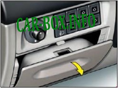
The distribution box is located on the driver's side, at the bottom of the dashboard, behind the plastic cover.
Type 1
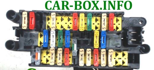
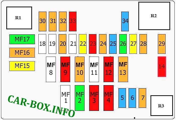
General view of the Citroen Xsara Picasso interior fuse box.
| Diagram | ||
|---|---|---|
|
||
| No. | Description | A |
| F1 | Front and side airbags, seatbelt pretensioners | Shunt |
| F2 | Not | - |
| F3 | Clutch pedal switch | 5 |
| F4 | "+" after ignition switch, multiplex system (BSI) | 5 |
| F5 | Power to engine stop valve (2.0 HDi) | 10 |
| F6 | Constant power supply for emergency light signaling | 5 |
| F7 | Multiplex continuous power supply (BSI) | 5 |
| F8 | Coolant temperature sensor, interior overhead lighting, instrument cluster | 10 |
| F9 | Luggage compartment lighting | 5 |
| F10 | Navigation | 5 |
| F11 | Not | - |
| F12 | Not | - |
| F13 | Not | - |
| F14 | Power supply to auxiliary socket and trailer electrical equipment | 15/30 |
| F15 | Rear door windows | 20 |
| F16 | Protection block | 40 |
| F17 | Car radio receiver | 15 |
| F18 | Not | - |
| F19 | Rear fog lamps | 5 |
| F20 | Not | - |
| F21 | Not | - |
| F22 | Ceiling lighting, glove box lighting | 10 |
| F23 | cigarette lighter fuse xsara picasso | 20 |
| F24 | Not | - |
| F25 | Not | - |
| F26 | Electrically operated mirrors | 5 |
| F27 | Continuous power supply for optional equipment and multiplex system (BSI) | 5 |
| F28 | Not | - |
| F29 | Left high beam headlamp | 10 |
| F30 | High beam headlight, right | 10 |
| F31 | Left low beam headlamp | 10 |
| F32 | RH low beam headlamp | 10 |
| F33 | Headlight corrector | 10 |
| F34 | License plate lighting, front left and rear right parking lights | 10 |
| F35 | Front right and rear left position lights | 10 |
| F36 | Air conditioning system | 15 |
| F37 | Not | five |
| F38 | Push button switch | five |
| F39 | Not | five |
| F40 | Air conditioning fan | 40 |
Additional board on the side
|
||
| 1 | Multiplex system power supply | 15 |
| 2 | Sunroof, front and rear power windows | 30 |
| 3 | Air conditioning compressor, rear window wiper | 15 |
| 4 | Heater for rear window and exterior mirrors | 30 |
| 5 | Windshield wiper | 25 |
| 6 | Central locking system | 20 |
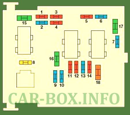
Type 2
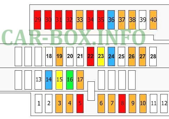
The second version of the interior fuse box.
| Diagram | ||
|---|---|---|
|
||
| No. | Description | A |
| 1 | Diagnostic socket - Tow hitch for towing a motorcaravan | 15 |
| 2 | Spare | - |
| 3 | Spare | - |
| 4 | Electronic Control Unit (ECU) - Instrument cluster - Car radio - Diesel fuel additives - Steering wheel control keys | 20 |
| 5 | - | 15 |
| 6 | Diagnostic connector | 10 |
| 7 | Rain and ambient light sensor | 15 |
| 8 | Spare | - |
| 9 | Sunroof - Rear Power Windows | 30 |
| 10 | Heated rear window - Heated exterior mirrors | 40 |
| 11 | Rear window wiper | 15 |
| 12 | Front electric windows | 30 |
| 13 | Spare | - |
| 14 | Steering wheel mounted control keys - Diesel fuel additives - Airbag - Parking sensors | 10 |
| 15 |
|
15 |
| 16 | Central electric lock | 30 |
| 17 | Spare | - |
| 18 | Spare | - |
| 19 | Spare | - |
| 20 | Right brake light | 10 |
| 21 | Left brake light | 15 |
| 22 |
|
20 |
In the engine compartment
Main fuse box

It is located on the right side of the underhood in the corner, closer to the windshield. Depending on the year of manufacture, its design may vary.
Type 1

General view.
| Diagram | ||
|---|---|---|
|
||
| No. | Description | A |
| 18 | - | |
| 16 | - | |
| 20 | Cooling fan motor relay | 5 |
| 21 | - | |
| 22 | Direction indicators | 20 |
| 23 | Anti-lock braking system (ABS) | 10 |
| 24 | Engine management | |
| 25 | 15 | |
| 26 | 30 | |
| 27 | Relay box | 20 |
| 28 | Reserve | 5 |
| 29 | Coolant heater | 40 |
| 30 | Fog lamp, right | 5 |
| 31 | Fog lamp, left | 5 |
| 32 | Vehicle speed sensor, reversing lamps | 5 |
| 33 | Low coolant temperature sensor, diagnostic connector, fuel heater | 10 |
| 34 | Engine management | 15 |
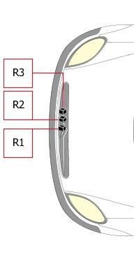
| R1 | Fog lamp relay | - |
| R2 | Auxiliary heater relay | - |
| R3 | Headlamp low beam relay | - |
| MF1 | Multifunctional control unit 1 | 70 |
| MF 2 | Cooling fan motor (low speed) | 30 |
| MF 3 | Cooling fan motor (high speed) | 30 |
| MF 4 | Anti-lock braking system (ABS) | 50 |
| MF 5 | Horn | 15 |
| MF 6 | Headlamp low beam relay | 15 |
| MF 7 | Cooling fan motor relay | 5 |
| MF 8 | Interior distribution box | 70 |
| MF 9 | Multifunctional control unit 1 | 50 |
| MF 10 | Headlight switch | 40 |
| MF 11 | - | |
| MF12 | Ignition lock | 50 |
| MF 13 | 40 | |
| MF14 | Diagnostic connector | 10 |
| MF 15 | Seat heater | 20 |
| MF 16 | Passenger compartment fuse box | 40 |
| MF 17 | Coolant heater | 30 |
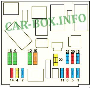
Type 2
The second version of the underhood unit design.
| Diagram | ||
|---|---|---|
|
||
| No. | Decoding | A |
| 1 | Reverse lights - Diesel fuel water sensor - Coolant | 10 |
| 2 | Fuel pump fuse | 15 |
| 3 | Electronic control unit (ECU) of the ABS system | 10 |
| 4 | Engine (ECU) - Automatic transmission ECU | 10 |
| 5 | BVA - Diesel Fuel Additives | 10 |
| 6 | Fog lights | 15 |
| 7 | Automatic lighting | 15 |
| 8 | Engine (ECU) | 20 |
| 9 | Low beam lamp, left headlight | 15 |
| 10 | Low beam lamp, right headlight | 15 |
| 11 | Left high beam headlamp | 10 |
| 12 | High beam headlight, right | 10 |
| 13 | Horn | 15 |
| 14 | Front and rear washers | 10 |
| 15 | Engine sensors, ignition coils, injectors, Solenoid valves | 30 |
| 16 | Air pump | 30 |
| 17 | Front wiper | 30 |
| 18 | air supply system actuator, service panel | 40 |
Additional board on the side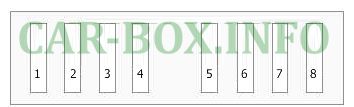
|
||
| 1 | Cooling fan motor relay | 50 |
| 2 | Anti-lock braking system (ABS) | 50 |
| 3 | Anti-lock braking system (ABS) | 30 |
| 4 | Multifunctional control unit 1 | 50 |
| 5 | Multifunctional control unit 1 | 50 |
| 6 | Heated seats | |
| 7 | Ignition lock | 50 |
| 8 | Air conditioning | 70 |
Auxilary fuse panel
Depending on the equipment, an additional board with relays and fuses may be located in the engine compartment (its right side).
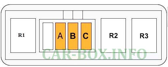
Here you will find 40A fuses and relay modules responsible for the air conditioner heater.
Individual relays
Some relay modules responsible for the radiator fan are located separately in the front of the engine compartment.

بارك الله فيك وربي يوفقك ويعطيك كل خير لأنه يساعدني كثيرا ويخفف عني متاعب التنقل للكشف عن بعض الأعطال البسيطة وشكرا
(God bless you and give you all the best because it helps me a lot and relieves me of the hassle of traveling to detect some minor malfunctions and thank you)