
The EcoSport mini crossover has been produced across two generations since 2003. The first generation was sold exclusively in Latin America. The second generation was distributed globally and manufactured from 2012 through 2022, receiving a mid-cycle refresh during this production run. This guide provides detailed fuse and relay box diagrams, location descriptions, and photos for the second-generation Ford EcoSport (B3-586 platform; chassis code B515).

The fuse for the "cigarette lighter" / auxiliary power socket is highlighted in bold.
Passenger Compartment Fuse Box

This fuse box is located behind the glove compartment. To access it:
- Open the glove compartment and remove all contents.
- Remove the four retaining screws, then remove the interior glove box shelf.
- Unclip the side trim panel.
- Remove the glove box assembly.
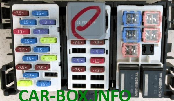
Passenger compartment fuse box photo
| Diagram | |
|---|---|
|
|
| No. | Circuit Protected |
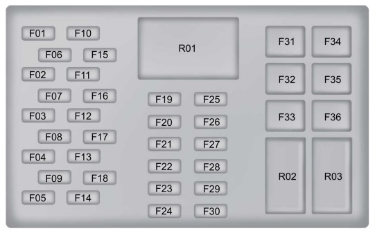
| F1 | 7.5 A – A/C compressor clutch, rain sensor module, auto-dimming interior rearview mirror |
| F2 | 10 A – Brake lights (stop lamps) |
| F3 | 7.5 A – Reverse lights (backup lamps) |
| F4 | 7.5 A – Headlight leveling control |
| F5 | 20 A – Windshield wiper motor |
| F6 | 15 A – Rear window wiper motor |
| F7 | 15 A – Windshield/rear window washer fluid pump |
| F8 | 15 A – Heated driver seat |
| F9 | 15 A – Heated passenger seat |
| F10 | 15 A – Ignition switch, push-button start switch, keyless entry accessory relay |
| F11 | 3 A – Instrument cluster |
| F12 | 15 A – OBD-II Data Link Connector (DLC) |
| F13 | 7.5 A – HVAC control module (manual/automatic climate control), anti-theft sensors, Remote Keyless Entry (RKE) receiver, audio control panel, front display control interface module reset |
| F14 | 15 A – Audio system, SYNC module, GPS module |
| F15 | 3 A – Power folding mirrors, front power window regulators |
| F16 | 20 A – Remote keyless entry system |
| F17 | 20 A – Remote keyless entry system |
| F18 | Not used |
| F19 | 7.5 A – Instrument cluster |
| F20 | Not used |
| F21 | 3 A – Passenger Airbag Deactivation (PAD) indicator lamp |
| F22 | 7.5 A – Heated exterior mirrors |
| F23 | Not used |
| F24 | Not used |
| F25 | 7.5 A – Climate control module, HVAC blower motor relay, front fog lights, engine block heater |
| F26 | 3 A – Supplemental Restraint System (SRS) airbag control module |
| F27 | 10 A – Park Assist button, Body Control Module (BCM), Passive Anti-Theft System (PATS), Anti-lock Braking System (ABS), ignition switch, instrument cluster, Electronic Power-Assisted Steering (EPAS), washer fluid pump |
| F28 | 7.5 A – Accelerator Pedal Position (APP) sensor, high-pressure fuel pump, Powertrain Control Module (PCM), Transmission Control Module (TCM) |
| F29 | Not used |
| F30 | Not used |
| F31 | 20 A – Cigarette lighter, front auxiliary power outlets (12V) |
| F32 | 20 A – Rear auxiliary power outlets (12V) |
| F33 | Not used |
| F34 | 30 A – Front power windows |
| F35 | 30 A – Rear power windows |
| F36 | Not used |
| R01 | Ignition relay |
| R02 | Push-button start relay |
| R03 | Keyless entry accessory relay |
| Fuse No. 31 (20 A) controls the cigarette lighter and front auxiliary power outlets on the Ford EcoSport. | |
Engine Compartment Fuse Box
Underhood Fuse Junction Box
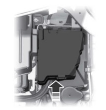
The main underhood fuse box is located on the driver’s side of the engine compartment, adjacent to the windshield washer fluid reservoir filler neck, under a protective plastic cover.
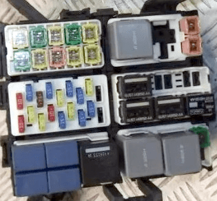
Engine compartment fuse box photo
| Diagram | |
|---|---|
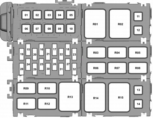
|
|
| No. | Circuit Protected |
| 1 | 60 A – Underhood fuse junction box |
| 2 | 40 A – Anti-lock Braking System (ABS) module |
| 3 | 60 A – Underhood fuse junction box, Powertrain Control Module (PCM) |
| 4 | 40 A – Climate control blower motor |
| 5 | 60 A – Passenger compartment fuse box |
| 6 | 30 A – Central locking system, anti-theft alarm system |
| 7 | 60 A – Ignition relay, passenger compartment fuse box |
| 8 | 30 A – Starter motor relay |
| 9 | 60 A – High-speed radiator cooling fan motor, underhood fuse box |
| 10 | 30 A / 40 A / 60 A – Transmission Control Module (TCM), glow plugs, low-speed radiator cooling fan (1.0L EcoBoost) |
| 11 | 30 A – Heated windshield (left side) |
| 12 | 30 A – Heated windshield (right side) |
| 13 | 30 A – Low-speed radiator cooling fan (1.5L Duratec 16V Ti-VCT / 1.5L Duratorq TDCi) |
| 14 | 30 A – Transmission Control Module (TCM) |
| 15 | 15 A – Battery Saver System, front fog lamps, high-beam headlights, interior lighting, right low-beam headlight, passenger airbag deactivation indicator lamp |
| 16 | 15 A – Left low-beam headlight, parking lamps, rear fog lamp, Daytime Running Lights (DRL) |
| 17 | 15 A – High-beam headlights |
| 18 | 20 A – Horn switch / alarm sounder |
| 19 | 20 A – Electric auxiliary water pump |
| 20 | 7.5 A – Transmission Control Module (TCM), Powertrain Control Module (PCM) |
| 21 | 20 A – Fuel pump and fuel injector relays |
| 22 | 15 A – Front fog lamps, high-beam headlights, interior lighting, turn signal indicators |
| 23 | 10 A / 15 A – Backup battery sounder, anti-theft alarm, horn relay |
| 24 | 20 A – Heated rear window (defroster), heated exterior mirrors |
| 25 | Air conditioning relay (including 1.0L EcoBoost models) |
| 26 | 20 A – Anti-lock Braking System (ABS) / Electronic Stability Control (ESC) module |
| 27 | 15 A – Front fog lamps |
| 28 | 10 A – Engine coolant pump |
| 29 | 15 A / 20 A – Ignition coils |
| 30 | 15 A – Radiator cooling fan relays (high/low speed), Powertrain Control Module (PCM), EVAP canister purge valve |
| 31 | 15 A – Cold-start solenoid valve, Heated Oxygen Sensor (HO2S); 20 A – Powertrain Control Module (PCM) (1.5L Duratorq TDCi) |
| 32 | Not used |
| Relay Identification | |
| R1 | High-speed radiator cooling fan relay |
| R2 | Glow plug relay |
| R3 | Front and rear fog lamp relays |
| R4 | Fuel pump relay (1.5L Duratorq TDCi) |
| R5 | Reverse lights (backup lamps) relay |
| R6 | High-beam headlight relay |
| R7 | Air conditioning control relay |
| R8 | Horn relay |
| R9 | Low-speed radiator cooling fan relay |
| R10 | Starter motor relay |
| R11 | Fuel pump relay (1.0L EcoBoost / 1.5L Duratec 16V Ti-VCT), diesel fuel heater relay (1.5L Duratorq TDCi) |
| R12 | HVAC blower motor relay |
| R13 | Powertrain Control Module (PCM) relay |
| R14 | Engine block heater relay |
| R15 | Engine block heater relay |
High-Current Battery Fuse Terminal
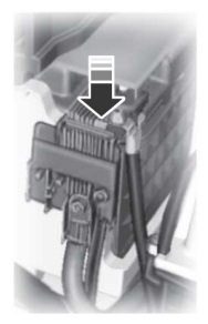
Mounted directly on the positive battery terminal, this panel contains high-amp fusible links.
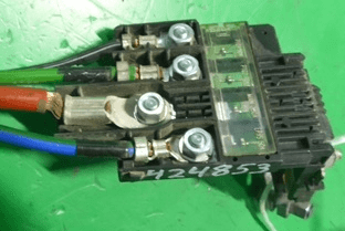
Battery power fuse panel photo
| Diagram | |
|---|---|

|
|
| No. | Circuit Protected |
| F1 | 450 A – Starter motor |
| F2 | 60 A – Electronic Power-Assisted Steering (EPAS) |
| F3 | 200 A – Underhood fuse junction box |
| F4 | 70 A – Engine block heater |
| F5 | 50 A – Engine block heater |
| F6 | 30 A – Battery Monitoring System (BMS) |
On select model configurations, inline thermal circuit breakers or separate fuses may be installed along the radiator cooling fan wiring harness.