Most of the electrical power circuits of American pickup and Jeep are protected by fuses. Powerful current consumers are connected via relays. Protective elements are installed in distribution boxes, which are located under the hood and in the passenger compartment.

The information provided in the diagrams refers to Ford Explorer (UN150, UN46, UN105) 1st and 2nd generation 1990, 1991, 1992, 1993, 1994, 1995, 1996, 1997, 1998, 1999, 2000, 2001, 2002, 2003 , 2004, 2005 release.
In the passenger compartment
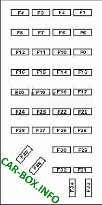
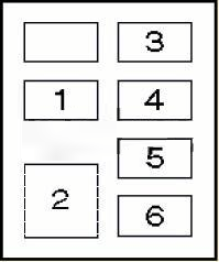
The main fuse box is located on the driver's side under the dashboard, an additional relay board is located behind the center console.
| Diagram (main box) | ||
|---|---|---|
|
||
| № | Decoding | A |
| F1 | Cigarette lighter, watch | 10 |
| F2 | Air conditioning / heating system | 10 |
| F3 | Front / rear / license plate lamps | 10 |
| F4 | Headlights, daytime running lights, front / rear / license plate lights | 15 |
| F5 | Diagnostic system | 10 |
| F6 | Engine management | 15 |
| F7 | Clock, instrument cluster illumination lamps, cigarette lighter | 10 |
| F8 | Headlights, daytime lighting system | 15 |
| F9 | - | |
| F10 | Active suspension system, brake lights, multifunction control unit, cruise control air conditioning / heating system | 10 |
| F11 | ABS system, 4WD system, interior lamps, instrument cluster, multifunction control unit, warning buzzer | 10 |
| F12 | Cleaners / Washers | 10 |
| F13 | ABS system, active suspension system, 4WD system, engine management system, brake lights, direction indicators, hazard warning lights, multifunction control unit, cruise control system | 15 |
| F14 | ABS | 10 |
| F15 | Charging system, instrument cluster, SRS system | 15 |
| F16 | Cleaners / Washers | 30 |
| F17 | Cigarette lighter, watch | 30 |
| F18 | Air conditioning / heating system | 15 |
| F19 | Engine management | 25 |
| F20 | Multifunctional control unit, cigarette lighter, clock, audio system | 10 |
| F21 | Direction indicators / hazard warning lights | 15 |
| F22 | Gate indicators / alarm | 15 |
| F23 | Cleaners / Washers | 15 |
| F24 | Launch system | 15 |
| F25 | Instrument cluster, multifunction control unit | 10 |
| F26 | 4WD System, Engine Management System, Daytime Lighting System, Reversing Lights, Heated Rear Window | 15 |
| F27 | 4WD system, interior lamps, door openings | 15 |
| F28 | 4WD system, starting system, wipers / washers, multifunction control unit | 10 |
| F29 | Audio system | 15 |
| F30 | - | |
| F31 | Front / rear / license plate lamps | 10 |
| F32 | Heated rear window | 10 |
| F33 | Headlights, daytime lighting system | 20 |
| F34 | Headlights, daytime lighting system | 15 |
| F35 | (15A) Fog lights | 15 |
| F36 | - | |
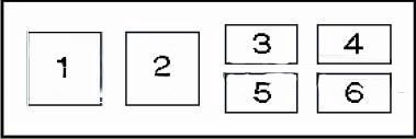
| Diagram (additional box) | |
|---|---|
|
|
| № | Description |
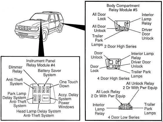
| 1 | Front / rear light relay |
| 2 | Power windows, sunroof, 4WD system relay |
| 3 | Anti-theft relay |
| 4 | Interior lamp relay |
| 5 | Relay for auxiliary ignition circuits |
| 6 | Power window relay (glass lowering) |
In engine compartment
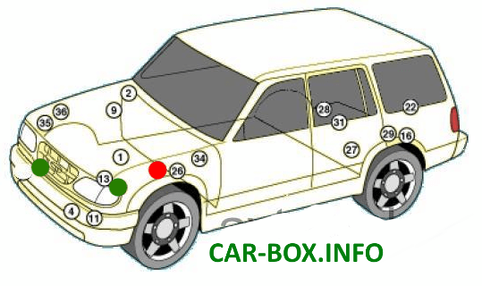
There are three blocks in the engine compartment: the main one is marked with a red dot, and two additional blocks are marked with green dots.
| Diagram of the main engine block | ||
|---|---|---|

|
||
| № | Description | A |
| F1 | Launch system | 60 |
| F2 | 60 | |
| F3 | Active suspension system | 50 |
| F4 | - | |
| F5 | 4WD system, power seat | 30 |
| F6 | Air conditioning / heating system | 50 |
| F7 | Front / rear / license plate lights, warning buzzer | 30 |
| F8 | Direction indicators / hazard warning lamps, front / rear / license plate lamps | 20 |
| F9 | ABS | 30 |
| F10 | ABS | 30 |
| F11 | Headlights, Daytime Lighting System, Fog Lights | 30 |
| F12 | Engine management | 20 |
| F13 | 30 | |
| F14 | Heated rear window | 30 |
| F15 | Cruise control, engine management, horns | 20 |
| F16 | 4WD control system | 20 |
| F17 | Charging system | 15 |
| F18 | Active suspension system | 15 |
| F19 | Airbags | 10 |
| F20 | Explorer cigarette lighter, watch | 30 |
| F21 | Cleaners / Washers | 15 |
| F22 | - | |
| 1 | Horn relay | |
| 2 | Daytime lighting relay | |
| 3 | Relay, electronic engine control unit | |
| 4 | Fuel pump relay | |
| 5 | Windshield wiper motor relay 1 | |
| 6 | Windshield wiper motor relay 2 | |
| 7 | Air conditioning compressor electromagnetic clutch relay | |
| 8 | Diode circuit of the electronic engine control unit | |
| 9 | Diode ABS | |
| 10 | Suspension control relay | |
| Аdditional block №2 | |
|---|---|
|
|
| № | Description |
| 1 | ABS pump relay |
| 2 | ABS relay |
| 3 | Trailer turn signal relay, right |
| 4 | Rear window motor relay - lower |
| 5 | Trailer left turn signal relay |
| 6 | Rear window motor relay - lifting |
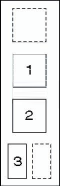
| Additional block №3 | |
|---|---|
|
|
| № | Appointment |
| 1 | Heater blower motor relay |
| 2 | Heater blower motor relay (high speed) |
| 3 | Windshield washer pump relay |
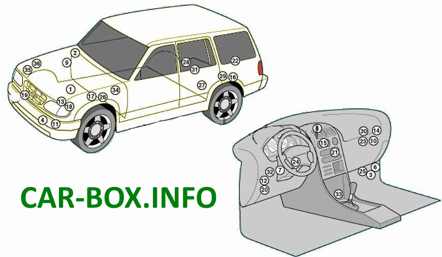
General layout
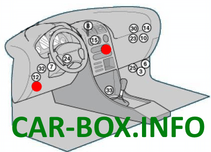
Location of the electronic modules
|
|
| № | Component |
| 1 | Air conditioning refrigerant pressure switch |
| 2 | Sensor switch for low pressure of refrigerant in the air conditioning system |
| 3 | SRS electronic control unit |
| 4 | Shock sensor, single (left) |
| 5 | Shock sensor, single (right) |
| 6 | SRS diagnostic connector |
| 7 | Brake lock control unit |
| 8 | Integrated relay / control unit |
| 9 | Cruise control (cruise control) control unit |
| 10 | Daytime lighting control unit |
| 11 | Daylight Resistor |
| 12 | Diagnostic connector |
| 13 | Diagnostic line (ignition) |
| 14 | Relay 1 system 4WD |
| 15 | Relay 2 system 4WD |
| 16 | Gasoline pump |
| 17 | Fuse box, engine compartment 1 |
| 18 | Relay box, engine compartment 2 |
| 19 | Relay box, engine compartment 3 |
| 20 | Instrument panel fuse box 1 |
| 21 | Dashboard relay box 2 |
| 22 | Fuse / relay box, luggage compartment |
| 23 | Heated rear window relay |
| 24 | Pointer block |
| 25 | Inertial fuel cut-off switch |
| 26 | Starter relay |
| 27 | Active suspension valve block 1, rear |
| 28 | Active suspension valve block 2, rear |
| 29 | Active suspension compressor |
| 30 | Suspension control unit |