Table of Contents
Most of the power supply circuits of the electrical equipment of the American crossover are protected by fuses. Powerful current consumers are connected via relays. Protective elements are installed in distribution boxes located under the hood and in the passenger compartment.
The information provided in the diagrams refers to Ford Explorer (U251) 4th generation 2005, 2006, 2007, 2008, 2009, 2010, 2011 models.
In the engine compartment

The fuse box is located on the right side of the engine compartment, behind the plastic cover.
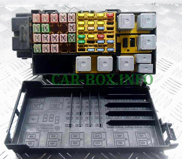
Photo - example.
| Diagram | ||
|---|---|---|
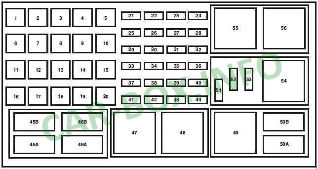
| 2007 - 2011 models | ||
|
||
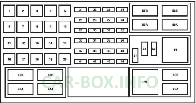
| 2005 - 2007 models | ||
|
||
| No. | Relay decoding | |
| 45 | No | |
| 45V | Fan GCC | |
| 46 | No | |
| 46B | No | |
| 47 | Front wiper | |
| 48 | RSM | |
| 49 | Fuel pump relay | |
| fifty | Fog lights and lights | |
| 50V | AC clutch relay | |
| 54 | Trailer battery charger relay | |
| 55 | Starter | |
| 55A | RSM | |
| 55B | Front wiper relay | |
| 56 | Blower fan | |
| 56A | ||
| 56B | Starter | |
| No. | Purpose of diodes | |
| 51 | No | |
| 52 | A / C coupling (diode) | |
| 53 | OTIS | |
| No. | Description of fuses | Current, A |
| 1 | WATT 2 (SJB) | 50 |
| 2 | WATT 3 (SJB) | 50 |
| 3 | WATT 1 (SJB) | 50 |
| 4 | Fuel pump, injectors | 30 |
| 5 | Third row seat (left side) | 30 |
| 6 | IVD module, ABS | 40 |
| 7 | Powertrain Control Module (PCM) | 40 |
| 8 | Heated windshield (left side) | 40 |
| 9 | Heated windshield (right side) | 40 |
| 10 | Power seat (right side) | 30 |
| 11 | Starter | 30 |
| 12 | Third row seat (right side) | 30 |
| 13 | Trailer Towing Battery Charger | 30 |
| 14 | Position memory (DSM) seats | 30 |
| Seats without memory function | 40 | |
| 15 | Heated rear window, heated mirrors | 40 |
| 16 | Blower fan motor | 40 |
| 17 | Electronic trailer brakes | 30 |
| 18 | Auxiliary blower motor | 30 |
| 19 | Footrests | 30 |
| 20 | 2008-2010: Front wiper | 30 |
| 21 | Rear power socket | 20 |
| 22 | Subwoofer | 30 |
| 23 | 4x4 all-wheel drive system | 30 |
| 24 | Powertrain control module (PCM) KAR, CAN ventilation | 10 |
| 25 | Front Power Socket / Cigarette Lighter | 20 |
| 26 | 4x4 system module | 20 |
| 27 | 6R - Transmission module | 20 |
| 28 | Heated seats, power mirrors | 20 |
| 29 | 2005-2006: Headlights (right side) | 20 |
| 2007-2010: Headlights (right side) | 15 | |
| 30 | Rear wiper | 25 |
| 31 | Fog lights / lights | 15 |
| 32 | Power mirrors | 5 |
| 33 | IVD module, ABS | 30 |
| 34 | 2005-2006: Headlights (left side) | 20 |
| 2007-2010: Headlights (left side) | 15 | |
| 35 | AC coupling | 10 |
| 36 | No | - |
| 37 | Front wiper (2005-2007), driver's door power window (2008-2010) | 30 |
| 38 | 5R - Gearbox | 15 |
| 39 | PCM power supply | 15 |
| 40 | Fan clutch, PCV valve, AC clutch relay, GCC fan | 15 |
| 41 | SDARS / DVD | 15 |
| 42 | Backup brake switch, EVMV, MAFS, HEGO, EVR, VCT1, VCT2, CMCV, CMS | 15 |
| 43 | Coil and spark plug assembly (4.6L engine only), ignition coil post (4.0L engine only) | 15 |
| 44 | Injectors | 15 |
In the passenger compartment
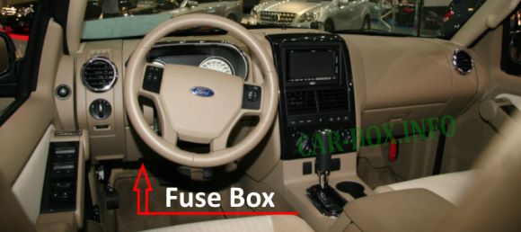
The fuse block is located on the driver's side, at the bottom of the dashboard.

Access example.
| Diagram | ||
|---|---|---|
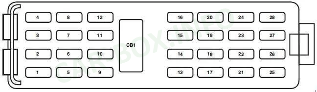
|
||
| No. | Description | A |
| 1 | Sunroof, adjustable pedals, DSM module, lumbar support motor with memory function | 20 |
| 2 | Microcontroller power supply (SJB) | 5 |
| 3 | Radio | 20 |
| 4 | 2005-2006 : OBDII connector | 20 |
| 2007-2010: OBDII connector | 10 | |
| 5 | Roof hatch | 5 |
| 6 | Power window motor, unlocking / locking doors | 20 |
| 7 | Brake lights, trailer turn signals | 15 |
| 8 | Ignition switch power supply, PATS | 15 |
| 9 | 6R TCM / PCM (position RUN / START ignition), fuel pump relay | 2 |
| 10 | Front wiper RUN / ACC position relay in PDB | 5 |
| 11 | Turning on the radio | 5 |
| 12 | RUN / ACC positions for rear wiper, trailer battery charging relay in PDB, radio | 5 |
| 13 | Heated mirrors, rear defrost indicator for manual climate control | 15 |
| 14 | Horn | 20 |
| 15 | Reversing lights | 10 |
| 16 | Trailer reversing lights | 10 |
| 17 | RCM, PAD lamp, OCS module | 10 |
| 18 | Reverse assist, IVD switch, IVD, 4x4 module, 4x4 switch, seat heating switches, compass, electrochromatic mirror, optional climate control system | 10 |
| 19 | No | - |
| 20 | Manual climate control, DEATC, brake pedal-dependent gearshift lock | 10 |
| 21 | No | - |
| 22 | Brake pedal shift lock, bi-color brake lights, CHMSL, all direction indicators | 15 |
| 23 | Interior lights, ambient lights, battery saver, instrument panel lights, Homelink | 15 |
| 24 | Instrument cluster, anti-theft alarm LED | 10 |
| 25 | Trailer parking lights, electronic trailer brake module | 15 |
| 26 | License plate light / rear parking light, front parking lights, manual climate control | 15 |
| 27 | Tricolor brake lights | 15 |
| 28 | Manually operated DEATC system | 10 |
| CB1 | Window lifters | 25 |
| No. | Purpose of relay modules | |
| R1 | ACC delay function | - |
| R2 | Heated rear window | - |
| R3 | Parking lights | - |
| R4 | RUN / START | - |
View and print PDF:
