The 5th generation Ford Mondeo began arriving in Europe in 2015. In the USA, it has been produced since 2012 under the name Fusion. Therefore, we can say that this model was sold all over the world in 2013, 2014, 2015, 2016, 2017, 2018, 2019 and 2020. During this time, the car was restyled 2 times. In our material you will find a description of fuse box and relays ford mondeo 5 (fusion usa). We will show the location of the blocks and their schemes with photo examples of execution. Separately, we will highlight the fuses responsible for the cigarette lighter and tell you how to find out the factory code from the door for keyless access to the salon.

Please note that the number of elements in blocks and their purpose may differ from yours and depends on the year of manufacture, the level of equipment and the country of delivery. Check the assignment against your diagram on the back of the protective cover.
In the passenger compartment
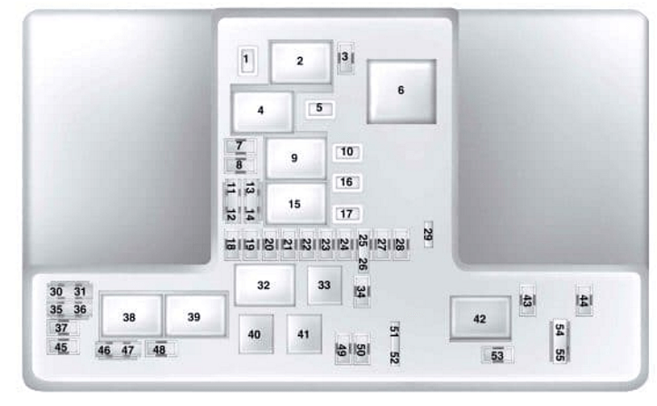
Fuse box
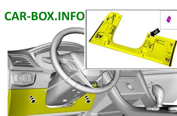
It is located on the left side of the dashboard and is combined with the BCM (body conrol module). For comfortable access, part of the protection must be removed.
| Photo diagram | |
|---|---|
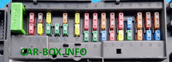
|
|
| № | Description |
| 1 | 10A Lighting, glove box lamp, vanity mirror lamp, ceiling lamp, luggage compartment lamp. |
| 2 | 7.5A Seat with memory function, lower backrest of the driver's seat, outside mirrors with electric drive. |
| 3 | 20A Unlocking the driver's door. |
| 4 | 5A Reserve |
| 5 | 20A Subwoofer Amplifier |
| 6 | 10A Reserve |
| 7 | 10A Reserve |
| 8 | 10A Anti-theft alarm horn |
| 9 | 10A Reserve |
| 10 | 5A Power Tailgate Module, Keypad, Mobile Phone Module |
| 11 | 5A General safety module |
| 12 | 7.5A Climate control, transmission |
| 13 | 7, A Steering column, dashboard, data connection |
| 14 | 10A Extended Power Module |
| 15 | 10A Data link gateway |
| 16 | 15A Childproof lock, luggage compartment lifting glass unlocking |
| 17 | 5A Buzzer for battery emergency power on |
| 18 | 5A Ignition switch, Ignition switch with start / stop push button |
| 19 | 7.5A Passenger airbag deactivation indicator, transmission |
| 20 | 7.5A Headlamp control module |
| 21 | 5A Interior thermometer. |
| 22 | 5A Reserve |
| 23 | 10A Auxiliary equipment off delay power supply circuit |
| 24 | 20A Central locking |
| 25 | 25A Driver's door and mirror |
| 26 | 30A Door and passenger mirror |
| 27 | 30A Moonroof |
| 28 | 20A Sound amplifier |
| 29 | 30A Rear door window, driver's side |
| 30 | 30A Rear door window, passenger side |
| 31 | 15A Reserve |
| 32 | 10A Global Positioning System Module, Voice Control, Display, Radio |
| 33 | 20A Radio receiver, noise control |
| 34 | 30А Bus "start / stop" (fuse 19, 20, 21, 22, 35, 36, 37, circuit breaker). |
| 35 | 5A Airbag and seat belt control module. |
| 36 | 15A Auto-dimming interior mirror, heated front and rear seat module, lane compliance monitoring system, automatic high beam. Climate controlled seats. |
| 37 | 15A All-wheel drive module. Heated steering wheel. |
| 38 | 30A Reserve |
How to find out the door code

4 ways to find out the factory door code (KEY CODE):
- Check the code in the documents on a separate card;
- The code can be found if you have two keys with the car. Put in the first key, turn on the ignition (but do not start the car), hold for 4 seconds, take out the key, put the second in and do the same. The factory code will appear on the dashboard;
- If the previous two points are not present, then the factory code can be found under the fuse box on the back;
- Read from a computer using a diagnostic cable.
In the engine compartment
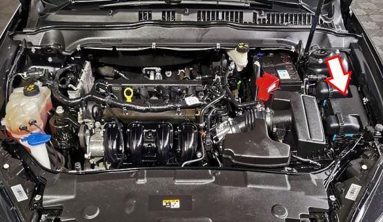
It consists of 2 sections and is located on the left side, next to the stand and is closed with a protective cover.
| Diagram (upper section) | |
|---|---|
|
|
|
|
| № | Description |
| 1 | 25A Windshield wiper 30A Hatch |
| 2 | Starter relay |
| 3 | 15A Automatic operation glass wipers, rain sensor, rear wipers |
| 4 | Electric blower relay |
| 5 | 20A Accessory power outlet on the back of the console |
| 6 | Auxiliary heater relay |
| 7 | 20A Powertrain control module |
| 8 | 20A Powertrain control module |
| 9 | Powertrain control module relay |
| 10 | 20A Front auxiliary power sockets, driver's side |
| 11 | 15A Powertrain control module |
| 12 | 15A Powertrain control module |
| 13 | 10A Powertrain control module |
| 14 | 10A Powertrain control module |
| 15 | Run / Start Relay |
| 16 | 20A Auxiliary power outlet on console, cigarette lighter |
| 17 | 20A Additional power socket in the luggage compartment |
| 18 | 10A Powertrain control module |
| 19 | 10A Power steering |
| 20 | 10A Illumination of the "start / stop" position, cruise control |
| 21 | 15A Transmission control module, transmission oil pump |
| 22 | 10A Air conditioning system |
| 23 | 15A. Start / stop, blind spot information system, rear view camera, adaptive cruise control, proximity warning, voltage quality module, air quality sensor |
| 24 | 10A Reserve |
| 25 | 10A Anti lock brake system, ABS |
| 26 | 10A Powertrain control module. |
| 27 | 10A Reserve |
| 28 | 10A Rear window washer pump. |
| 29 | 5A Air mass meter |
| 30 | Reserve |
| 31 | Reserve |
| 32 | Cooling fan relay |
| 33 | Air conditioning relay |
| 34 | 15A Electric steering column lock. |
| 35 | Reserve |
| 36 | Reserve |
| 37 | Reserve |
| 38 | Cooling fan relay |
| 39 | Cooling fan relay |
| 40 | Horn relay |
| 41 | Horn relay |
| 42 | Fuel pump relay |
| 43 | Rezrv |
| 44 | 5A Heated washer spray |
| 45 | Reserve |
| 46 | 10A Generator |
| 47 | 10A Brake Switch |
| 48 | 20A Buzzer |
| 49 | 5A Air flow sensor 20A Heating element for diesel fuel |
| 50 | 10A Cooling fan, transfer case 20A Signal |
| 51 | Reserve |
| 52 | Reserve |
| 53 | 10A Power seats. |
| 54 | 5A Remote control for fuel-fired heater, 10A Brake switch |
| 55 | 10A ALT sensor |
| For the operation of Ford Fusion cigarette lighters and USB sockets, fuses 17, 16, 10 and 5 at 20A are responsible. | |
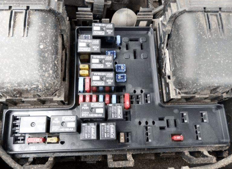
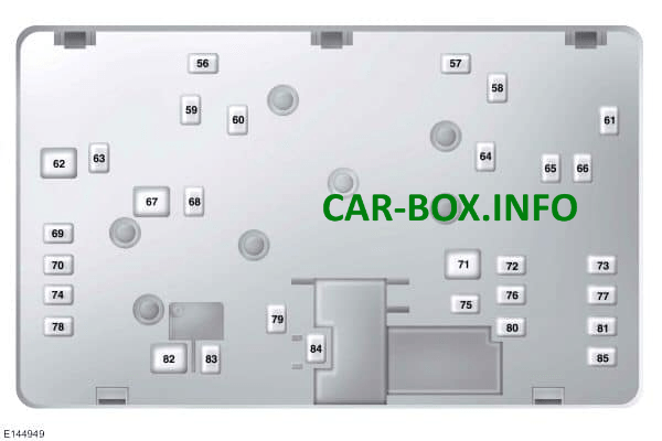
| Diagram (lower section) | |
|---|---|
Access example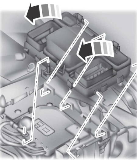
|
|
|
|
| № | Description |
| 56 | 30A Fuel pump |
| 57 | 20A Diesel fuel vaporizer |
| 58 | Reserve |
| 59 | 30 / 40A Cooling Fan (DW10F and 2.0L GTDI AU) |
| 60 | 30 / 40A Cooling Fan (DW10F and 2.0L GTDI AU) |
| 61 | 40A Heated windshield (left side) |
| 62 | 50A Body systems control unit |
| 63 | 20 / 30A Cooling Fan (DW10F and 2.0L GTDI AU) |
| 64 | 30A Additional heater |
| 65 | 20A. Heated front seats |
| 66 | 40A Heated windshield (right side) |
| 67 | 50A Body systems control unit |
| 68 | 40A Heated rear window |
| 69 | 30A Anti lock brake system |
| 70 | 30A Passenger seat |
| 71 | 60A Additional heater |
| 72 | 20A Fuel pump 30A Hatch |
| 73 | 20A Rear heated seat |
| 74 | 30A Driver's seat module |
| 75 | 30A Additional heater |
| 76 | 20A transmission oil pump |
| 77 | 30A Climate-controlled seat module |
| 78 | 40A Trailer towing module |
| 79 | 40A Electro blower fan. |
| 80 | 30A Power module in the luggage compartment. |
| 81 | 40A Inverter 220 V. |
| 82 | 60A Anti-lock brake system pump. |
| 83 | 25A Cleaner motor |
| 84 | 30A Starter solenoid. |
| 85 | 20A Fuel-fired heater 60A Anti-lock brake pump |
