
Table of Contents
The compact Ford Ranger pickup was produced in North America until 2013 across three generations. Following this, Ford introduced the updated global Ford Ranger T6. This article provides a detailed breakdown of the fuse and relay boxes for the Ford Ranger T6 (chassis code P375), covering model years 2011, 2012, 2013, 2014, 2015, and 2016. The fuse responsible for the “Cigarette lighter” is highlighted in bold.

Engine Compartment

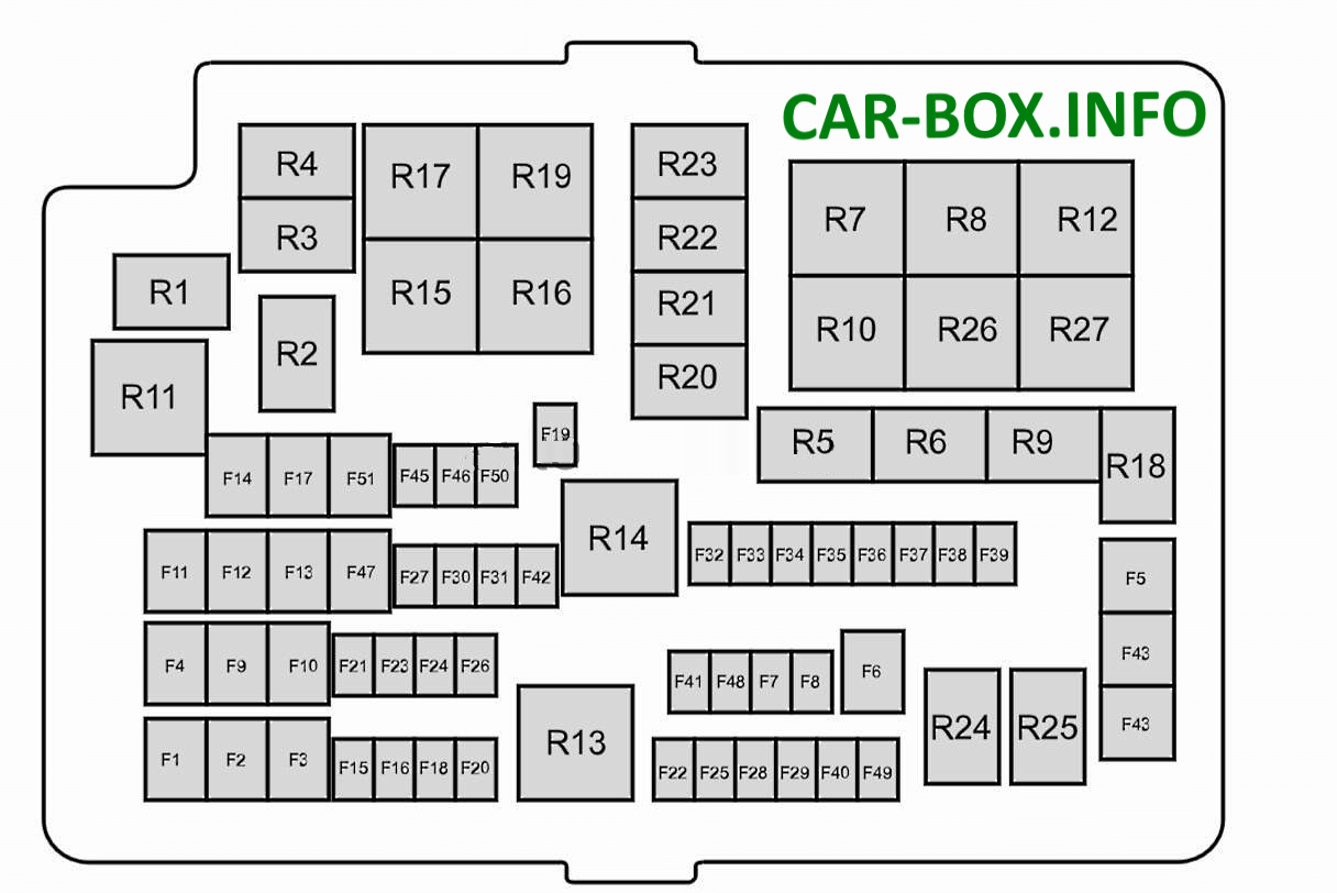
To access the fuse and relay box, squeeze the retaining latches and remove the cover.
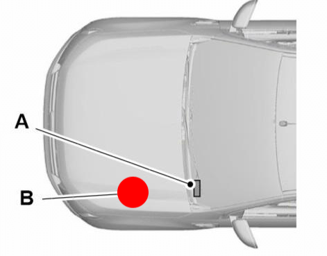
Location indicated by red dot
| Diagram | ||
|---|---|---|
|
||
| No. | Description | A |
| 1 | Passenger compartment fuse box power supply (Battery) | 60 |
| 2 | Passenger compartment fuse box power supply (Ignition) | 60 |
| 3 3 |
Gasoline engines – Engine cooling fan motor | 50 |
| Diesel engines – Glow plug control module | 60 | |
| 4 | Anti-lock Braking System (ABS) module | 40 |
| 5 | Power windows (front and rear) | 30 |
| 6 | Four-wheel drive (4WD) transfer case motor ground | 25 |
| 7 | Not used | - |
| 8 | Not used | - |
| 9 | Power seat adjustment | 20 |
| 10 | Power windows (front) | 30 |
| 11 | HVAC blower motor | 30 |
| 12 | Four-wheel drive (4WD) transfer case motor power | 25 |
| 13 | Starter motor solenoid relay coil | 20 |
| 14 | Heated rear window | 20 |
| 15 | Gasoline engines – Fuel pump | 10 |
| 15 | Diesel engines – Fuel vaporizer glow plug | 15 |
| 16 | A/C compressor clutch | 10 |
| 17 | Power windows (front) | 25 |
| 18 | Windshield wiper motor | 20 |
| 19 | Windshield wiper motor ground | 20 |
| 20 | Cigarette lighter | 20 |
| 21 | Horn | 15 |
| 22 | Fuel injectors / Fuel metering valve | 15 |
| 23 | Electronic locking differential solenoid | 10 |
| 24 | Auxiliary power outlet | 20 |
| 25 | Ignition coils, Mass Air Flow (MAF) sensor, temperature sensor, glow plug control module, Vacuum Control Valve (VCV), Electronic Vacuum Regulator Valve (EVRV) | 15 |
| 26 | Engine Control Module (ECM) | 7.5 |
| 27 | Transmission Control Module (TCM) | 10 |
| 28 | Heated Oxygen Sensor (HO2S), Universal Heated Oxygen Sensor, relay coils, fuel shutoff switch | 10 |
| 29 | Engine Control Module (ECM) | 15 |
| 30 | Battery Monitoring Sensor (BMS) | 15 |
| 31 | Auxiliary power outlet (rear console) | 20 |
| 32 | A/C pressure transducer | 5 |
| 33 | Transmission Control Module (TCM) | 10 |
| 34 | Not used | - |
| 35 | Passenger compartment fuse box power supply (Ignition) | 20 |
| 36 | Anti-lock Braking System (ABS) module | 5 |
| 37 | Headlamp leveling system | 10 |
| 38 | Heated seats | 20 |
| 39 | Power exterior mirrors | 10 |
| 40 | Evaporative emissions (EVAP) purge pump | 10 |
| 41 | Heated exterior mirrors | 10 |
| 42 | Security horn / Alarm siren | 10 |
| 43 | Heated windshield (right side) | 30 |
| 44 | Heated windshield (left side) | 30 |
| 45 | Anti-lock Braking System (ABS) module | 25 |
| 46 | Auxiliary power outlet (cargo bed) | 20 |
| 47 | Trailer tow control module | 40 |
| 48 | Not used | - |
| 49 | Not used | - |
| 50 | Ignition relay, ignition coils | 5 |
| 51 | Brazil models only – Power windows (rear) | 30 |
| 51 | Trailer tow connector (12-pin or 13-pin, battery constant) | 20 |
| No. | Relays | - |
| R1 | Ignition switch lock | - |
| R2 | Windshield wiper run/stop switch | - |
| R3 | Horn | - |
| R4 | A/C compressor clutch | - |
| R5 | Electronic locking differential | - |
| R6 | Windshield wiper high/low speed | - |
| R7 | Engine cooling fan (low speed) | - |
| R8 | Engine cooling fan (high speed) | - |
| R9 | Fuel pump, fuel vaporizer glow plug | - |
| R10 | Heated rear window | - |
| R11 | Heated windshield | - |
| R12 | Not used | - |
| R13 | ECM main power relay | - |
| R14 | Ignition system relay | - |
| R15 | 4WD transfer case motor 2 (clockwise) | - |
| R16 | 4WD transfer case motor 1 (counterclockwise) | - |
| R17 | 4WD transfer case motor | - |
| R18 | Security horn / Alarm siren | - |
| R19 | Starter motor | - |
| R20 | Not used | - |
| R21 | Not used | - |
| R22 | Not used | - |
| R23 | Not used | - |
| R24 | Not used | - |
| R25 | Not used | - |
| R26 | HVAC blower motor | - |
| R27 | Power seat adjustment | - |
Passenger Compartment
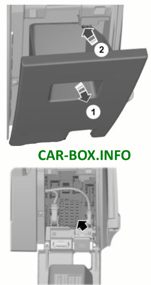
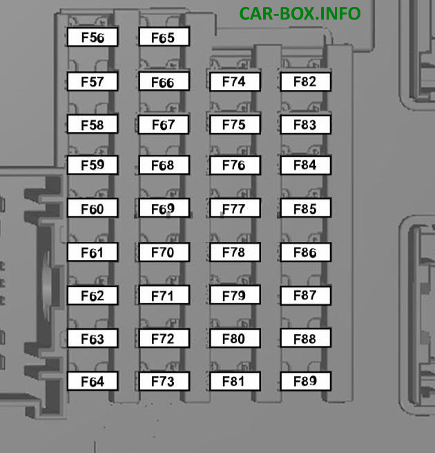
Located under the dashboard.
| Diagram | ||
|---|---|---|
|
||
| No. | A | Protected circuit |
| 56 | 20 | Fuel pump |
| 57 | - | Not used |
| 58 | - | Not used |
| 59 | 5 | Passive Anti-Theft System (PATS) |
| 60 | 10 | Interior lighting, driver door switch pack, ambient lighting, lower interior lighting, gearshift selector illumination, footwell lamps |
| 61 | - | Not used |
| 62 | 5 | Rain sensor module |
| 63 | 5 | Tachograph |
| 64 | - | Not used |
| 65 | - | Not used |
| 66 | 20 | Driver door lock, central double locking system |
| 67 | 5 | Brake pedal position (BPP) switch |
| 68 | - | Not used |
| 69 | 5 | Instrument cluster, Integrated Control Panel (ICP), shift interlock module |
| 70 | 20 | Central locking system |
| 71 | 5 | Air conditioning |
| system | ||
| 72 | 7.5 | Security horn / Alarm siren |
| 73 | 5 | On-Board Diagnostics (OBD-II) data link connector |
| 74 | 20 | High beam headlamps |
| 75 | 15 | Front fog lamps |
| 76 | 10 | Reverse lamps, auto-dimming rearview mirror |
| 77 | 20 | Windshield washer pump |
| 78 | 5 | Ignition switch (start and run) |
| 79 | 15 | Audio unit / Radio |
| 80 | 20 | Multi-function display, audio unit, Bluetooth/Voice Control (BVC) module |
| 81 | 5 | Interior motion sensor |
| 82 | 20 | Windshield washer pump ground |
| 83 | 20 | Central locking system ground |
| 84 | 20 | Driver door lock ground, central double locking system |
| 85 | 7.5 | Instrument cluster, parking aid module, rearview camera, manual climate control, auto-dimming rearview mirror |
| 86 | 10 | Supplemental Restraint System (SRS) airbags and seatbelts, passenger airbag deactivation switch |
| 87 | 5 | Tachograph |
| 88 | - | Not used |
| 89 | - | Not used |
Cargo Bed / Auxiliary Box

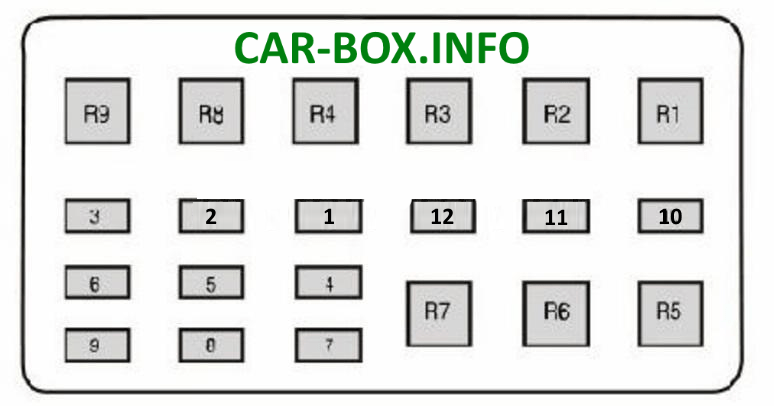
Location
| Diagram | ||
|---|---|---|
|
||
| No. | Description | A |
| 1 | High beam headlamps | 25 |
| 2 | Position / Side marker lamps | 15 |
| 3 | LED beacon / Strobe | 10 |
| 4 | Work lamps | 15 |
| 5 | Spare | 20 |
| 6 | Auxiliary power outlet | 20 |
| 7 | Reverse lamps | 15 |
| 8 | Turn signal lamps, stop lamps | 15 |
| 9 | Ford Crew Chief™ telematics system | 5 |
| 10 | Transit fuse (battery isolation) | 5 |
| 11 | Not used | - |
| 12 | Not used | - |
| R1 | Work lamps | - |
| R2 | LED beacon / Strobe | - |
| R3 | Spare | - |
| R4 | Position / Side marker lamps | - |
| R5 | Turn signal lamp (left) | - |
| R6 | Turn signal lamp (right) | - |
| R7 | Stop lamps | - |
| R8 | Not used | - |
| R9 | Not used | - |
