Chevrolet Orlando (J309) is a family car made on a platform common with the Chevrolet Cruze. Sold in 2010, 2011, 2012, 2013, 2014, 2015, 2016, 2017, 2018.

We provide information on Orlando fuse circuits and a complete description of all blocks. Let's show which fuse is responsible for the cigarette lighter and how to change it.
In the engine compartment
Main fuse box
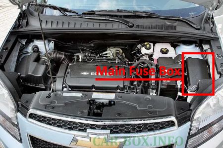
It is located on the left side of the engine compartment, next to the battery.
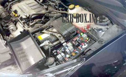
For access, you need to move the 3 latches on the cover and remove it.
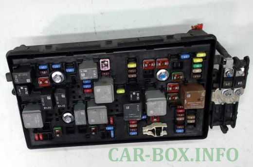
General view of the main fuse box.
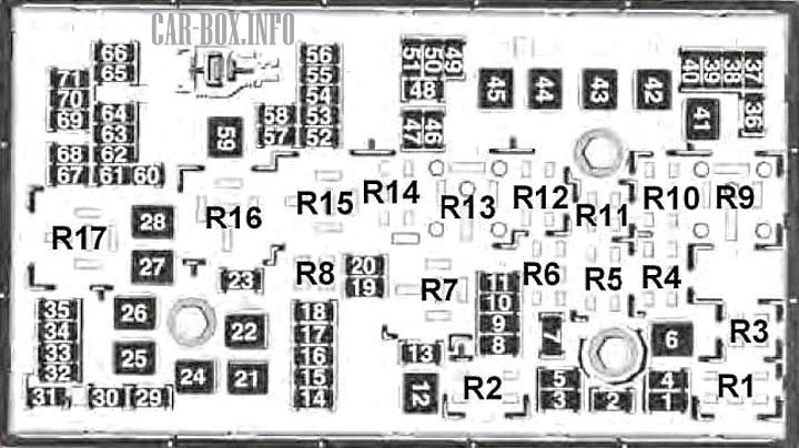
| Diagram | ||
|---|---|---|
|
||
| No. | Amps | Description |
| 1 | 15 | Transmission control module |
| 2 | 15 | Engine control module |
| 3 | - | Not used |
| 5 | 15 | Transmission Control Module, Engine Control Module, MAF / IAT Sensor, Transmission Output Shaft Speed Sensor |
| 6 | 30 | Windscreen wiper relay |
| 7 | - | Not used |
| 8 | 15 | Fuel injectors |
| 9 | 15 | Ignition coil, fuel injectors |
| 10 | 15 | Engine Control Module, Transmission Output Shaft Speed Sensor |
| 11 | 10 | Heated lambda sensors |
| 12 | 30 | Starter motor |
| 13 | 7.5 | Evaporative emission (EVAP) canister outlet solenoid valve |
| 14 | - | Not used |
| 15 | - | Not used |
| 16 | 7.5 | Air quality sensor |
| 17 | 5 | Airbag diagnostic and monitoring module |
| 18 | 10 | Fuel pump control module |
| 19 | - | Not used |
| 20 | 20 | Fuel pump relay |
| 21 | 30 | Window motors, front door |
| 22 | - | Not used |
| 23 | - | Not used |
| 24 | 30 | Window motors, front door |
| 25 | - | Not used |
| 26 | 40 | Electronic brake control unit (EBCM) |
| 27 | 30 | Receiver for door lock remote control |
| 28 | 40 | Rear defogger mesh |
| 29 | - | Not used |
| 30 | 15 | Electronic brake control unit (EBCM) |
| 31 | 20 | Body controller |
| 32 | 20 | Body controller |
| 33 | 30 | Seat heating control module |
| 34 | 25 | Roof sunroof control module |
| 35 | 30 | Audio amplifier |
| 36 | - | Not used |
| 37 | 10 | Headlamp - Right High Beam |
| 38 | 10 | Headlamp - left high beam |
| 39 | - | Not used |
| 40 | - | Not used |
| 41 | - | Not used |
| 42 | 20/30 | Radiator fan relay, radiator fan motor |
| 43 | - | Not used |
| 44 | - | Not used |
| 45 | 30/40 | Radiator fan high speed relay, radiator fan motor |
| 46 | 10 | Cooling fan relay |
| 47 | 10 | Heated oxygen sensors, throttle body |
| 48 | 15 | Fog lights, front |
| 49 | - | Not used |
| 50 | - | Not used |
| 51 | 15 | Sound signal |
| 52 | 5 | Instrument cluster |
| 53 | 10 | Interior rearview mirror |
| 54 | 5 | Headlamp switch, electric auxiliary heater, heating, ventilation and air conditioning control module |
| 55 | 7.5 | Window switches, front, mirror switch |
| 56 | 15 | Windshield washer pump |
| 57 | 15 | Steering column lock control module |
| 58 | - | Not used |
| 59 | 30 | Fuel heater |
| 60 | 7.5 | Exterior mirrors |
| 61 | - | Not used |
| 62 | 10 | A / C Compressor Clutch Relay, A / C Compressor Clutch |
| 63 | - | Not used |
| 64 | 5 | Airbag diagnostic and monitoring module |
| 65 | - | Not used |
| 66 | - | Not used |
| 67 | 20 | Fuel pump control module |
| 68 | - | Not used |
| 69 | 5 | Body controller |
| 70 | 5 | Rain sensor |
| 71 | - | Not used |
| Relay | ||
| R1 | Air Conditioning Compressor Clutch | |
| R2 | Starter | |
| R3 | Cooling Fan | |
| R4 | Windscreen wiper speed control | |
| R5 | Windshield wiper | |
| R6 | Not used | |
| R7 | Transmission | |
| R8 | Fuel pump | |
| R9 | Cooling fan 1 average speed | |
| R10 | Cooling fan 2 medium speed | |
| R11 | Not used | |
| R12 | Cooling fan speed control (or in the relay box - under the hood) | |
| R13 | Cooling Fan High Speed Relay | |
| R14 | Not used | |
| R15 | Main ignition relay | |
| R16 | Fuel heater relay | |
| R17 | Rear window defogger | |
| Note: The relays listed below are maintenance-free printed circuit board (PCB) relays located inside the unit. | ||
| - | Horn relay | |
| - | Windshield washer pump relay | |
| - | Front fog lamp relay | |
| - | Headlamp high beam relay | |
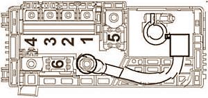
High power box
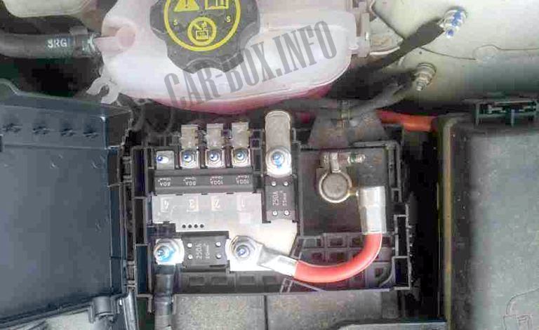
It is located on the battery cover.
| Diagram | ||
|---|---|---|
|
||
| No. | Amps | Description |
| 1 | 100 | Fuse Box - Instrument Panel |
| 2 | 100 | |
| 3 | 80 | Electric Power Steering (EPS) (NJ1) |
| 4 | - | Not used |
| 5 | 250 | Fuse Box - Additional Battery |
| 6 | 250/500 | Starter motor |
Additional relay box
Depending on the configuration, there may be a separate unit with a relay under the hood.
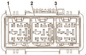
1 - Cooling fan low speed relay;
2 - Cooling fan low speed relay;
3 - Cooling fan speed control relay.
In the passenger compartment
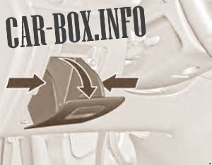
Fuse box is located behind the glove box in the dashboard.
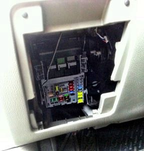
To access, squeeze from the sides, and then pull, lifting it up.
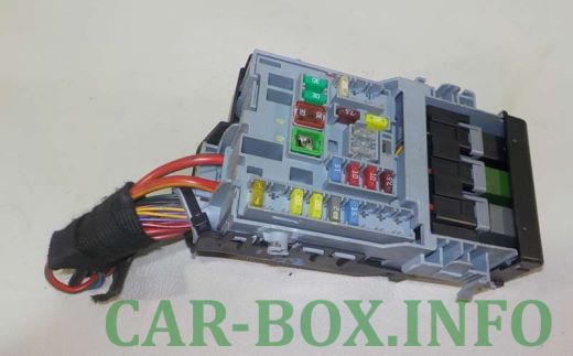
General view.
| Diagram | ||
|---|---|---|

|
||
| No. | Amps | Description |
| 1 | - | Not used |
| 2 | - | Not used |
| 3 | 25 | Body controller |
| 4 | 20 | Radio |
| 5 | 7.5 | Parking aid control module, sounder, steering column switch - center console, display |
| 6 | 20 | Orlando cigarette lighter |
| 7 | 20 | Power socket |
| 8 | 30 | Body controller |
| 9 | 30 | Body controller |
| 10 | 30 | Body controller |
| 11 | 40 | Door control module, Electric fan |
| 12 | - | Not used |
| 13 | 25 | Seat heating control module |
| 14 | 7.5 | Block diagnostics, oil supply connection |
| 15 | 10 | Airbag diagnostic and monitoring module |
| 16 | 10 | Rear compartment door release relay |
| 17 | 15 | HVAC control unit / HVAC control panel assembly |
| 18 | - | Not used |
| 19 | - | Not used |
| 20 | - | Not used |
| 21 | 15 | Instrument cluster |
| 22 | 2 | Ignition switch |
| 23 | 20 | Body controller |
| 24 | 20 | Body controller |
| 25 | - | Not used |
| 26 | 20 | Auxiliary power outlet |
Relay inside the unit:
- Tailgate;
- Logistic Mode;
- Auxiliary power supply.
