Most of the power supply circuits of the Japanese crossover electrical equipment are protected by fuses. Headlights, fan motors, fuel pump and other powerful current consumers are connected via relays. Protective elements are installed in mounting blocks located in the vehicle interior and engine compartment.

Considered models Toyota Fortuner (AN50, AN60) 2004, 2005, 2006, 2007, 2008, 2009, 2010, 2011, 2012, 2013, 2014, 2015 release.
In the engine compartment
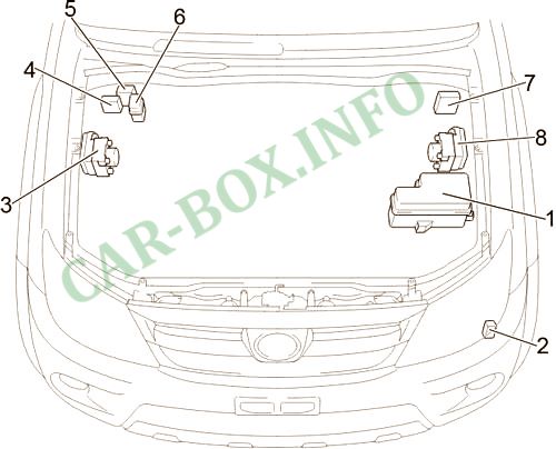
Location of components: 1. Fuse box; 2. Relay for headlight cleaners; 3. Right hand drive: Brake control unit; 4. Left hand drive: Injector control unit (EDU); 5. Air supply control unit; 6. Relay for cooling fan (CDS FAN); 7. Right hand drive: Injector control unit (EDU); 8. Left hand drive: Brake control unit.
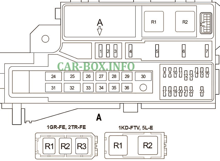
Fuse box
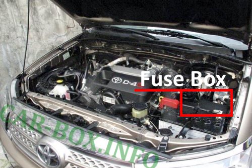
Photo location.
| Diagram | ||
|---|---|---|
|
||
| No. | Description | A |
| 1 | Spare | 25 |
| 2 | 15 | |
| 3 | 10 | |
| 4 | Front fog lamps | 15 |
| 5 | Horn | 10 |
| 6 | Multiport fuel injection system / sequential multiport fuel injection system | 25 |
| 7 | Empty | - |
| 8 | Up to 06.2011: Right-hand Headlamp (low beam) | 20 |
| From 06.2011: Right-hand Headlamp (low beam) | 15 | |
| 9 | Up to 06.2011: Left-hand Headlamp (low beam) | 20 |
| From 06.2011: LH Headlamp (low beam) | 15 | |
| 10 | Up to 06.2011: Right-hand Headlamp (high beam) and right-hand Headlamp (low beam) | 20 |
| From 06.2011: RH Headlamp (high beam) and RH Headlamp (low beam) | 15 | |
| 11 | Up to 06.2011: LH Headlamp (high beam) and LH Headlamp (low beam) | 20 |
| From 06.2011: LH Headlamp (high beam) and LH Headlamp (low beam) | 15 | |
| 12 | Until 08.2013: Multiport fuel injection system / sequential multiport fuel injection system | 7.5 |
| From 08.2013: Multiport fuel injection system / sequential multiport fuel injection system | 10 | |
| 13 | Empty | - |
| 14 | Before 08.2008: Door light switches, central locking, wireless control system, steering sensor, headlights | 7.5 |
| From 08.2008: Door light switches, central locking, wireless control, steering sensor, headlights | 10 | |
| 15 | Before 08.2013: Audio system | 15 |
| From 08.2013: Audio system | 20 | |
| 16 | Interior lamps, personal lamps, instrument cluster, clock, multifunction display, wireless control system, daytime running lamps, fog lamps | 7.5 |
| 17 | Exhaust gas emission control system | 20 |
| 18 | Multiport fuel injection system / sequential multiport fuel injection system | 10 |
| 19 | Charging system | 7.5 |
| 20 | Hazard warning lamps, direction indicators (turn signal / flasher) | 15 |
| 21 | Empty | - |
| 22 | Air conditioning | 7.5 |
| 23 | Fuses: "ECU-B", "DOME", "RAD" | 30 |
| 24 | 1KD-FTV, 5L-E: Auxiliary heater | 50 |
| 1GR-FE: Headlamp cleaners | 50 | |
| 25 | Heated seats | 30 |
| 26 | Cooling fan | 30 |
| 27 | Before 08.2008: ABS, TRC, VSC | 40 |
| From 08.2008: Rear air conditioner | 40 | |
| 28 | Before 08.2009: Air conditioning, fuse: "A / C" | 40 |
| From 08.2009: Air conditioning system, fuse: "A / C" | 50 | |
| 29 | ABS, TRC, VSC | 40 |
| 30 | Before 08.2008: Rear air conditioner | 30 |
| From 08.2008: ABS, TRC, VSC | 40 | |
| 31 | Charging system, fuses: "PWR SEAT", "HLP CLN", "FR HTR", "AM1", "IG1", "PTC NO.1", "PTC NO.2", "PWR OUT", "STOP" , "TAIL", "OBD" | 100 |
| 32 | Preheating system | 80 |
| 33 | Fuses: "FOG", "HORN", "EFI" | 50 |
| 34 | Starter, "ST", "IGN", "INJ", "MET" | 30 |
| 35 | Fuses: "H-LP RH", "H-LP LH", "H-LP RL" "H-LP LL" | 40 |
| 36 | 2TR-FE: Multiport fuel injection system / sequential multiport fuel injection system | 50 |
| 1KD-FTV: Headlamp cleaners | 50 | |
| Relay | ||
| R1 | Dimmer (DIM) (Headlamp switch) | |
| R2 | HID: Headlams Halogen: Cooling fan |
|
| or | ||
| R1 | Starter | |
| R2 | 1GR-FE, 2TR-FE : Air Fuel Ratio (A / F) Sensor 1KD-FTV, 5L-E : Glow Plugs (GLOW) |
|
| R3 | 1GR-FE, 2TR-FE: Fuel pump relay | |
In the passenger compartment
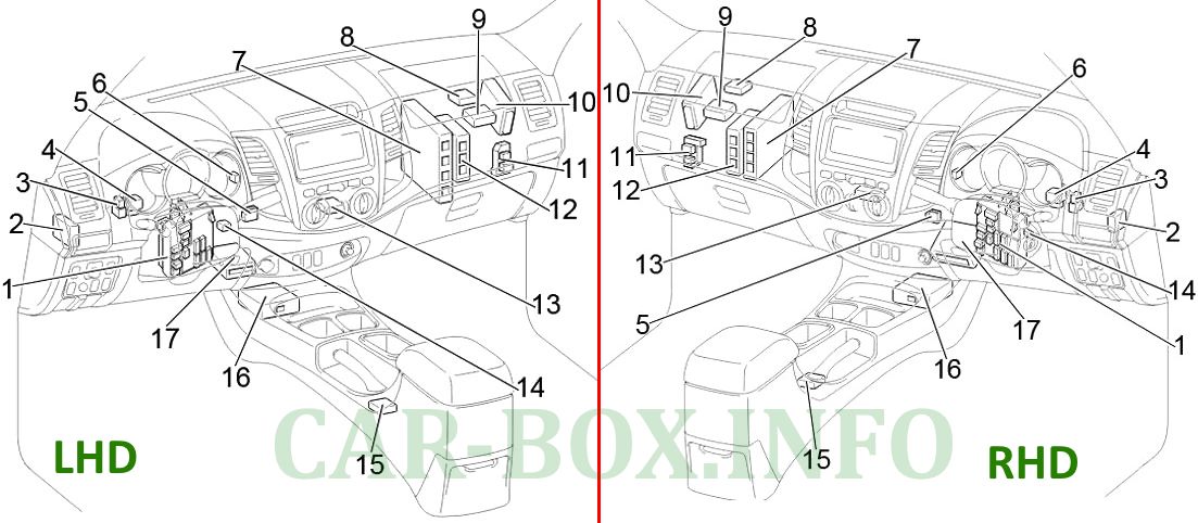
Location of components : 1. Fuse box; 2. Four-wheel drive control unit (rear differential lock); 3. Relay for air conditioning compressor clutch; 4. Relay of direction indicators; 5. Distribution connector (CAN); 6. Side light relay; 7. Engine control unit; 8. Receiver for central locking; 9. Control unit for headlight range control; 10. Anti-theft system control unit; 11. Relay box; 12. Transmission control unit; 13. Air conditioning control unit; 14. Key transponder amplifier; 15. Control unit for blocking the gear selector; 16. Airbag control unit; 17. Air conditioner amplifier.
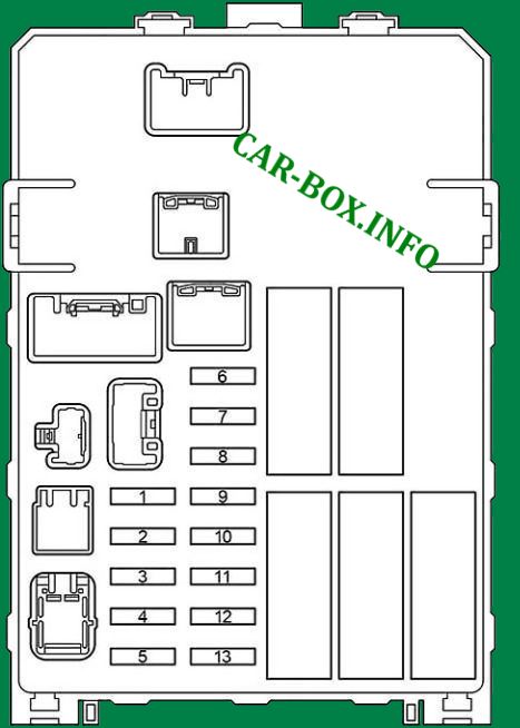
Fuse box #1
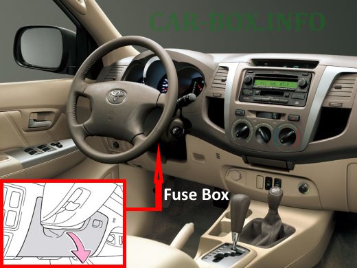
Photo location (LHD).
| Diagram | ||
|---|---|---|
|
||
| No. | Decoding | A |
| 1 | Multiport fuel injection system / sequential multiport fuel injection system | 15 |
| 2 | Diagnostic connector | 7.5 |
| 3 | Stop lamps, auxiliary brake light, multiport fuel injection system / sequential multiport fuel injection system, ABS, TRC, VSC, gear selector lock | 10 |
| 4 | Instrument panel illumination, front fog light, headlight range control, side light, license plate light, multiport fuel injection system / sequential multiport fuel injection system, multi-information display, daytime running lights, automatic lighting system | 10 |
| 5 | Power Outlet | 15 |
| 6 | Starting system, instrument cluster, multiport fuel injection system / sequential multiport fuel injection system | 7.5 |
| 7 | Air conditioning | 10 |
| 8 | Instrument cluster, DPF system | 7.5 |
| 9 | Cigarette lighter fuse Toyota Fortuner | 15 |
| 10 | Audio system, power outlet, clock, power mirrors, gear selector lock, multi-information display | 7.5 |
| 11 | Multiport fuel injection system / sequential multiport fuel injection system, airbags, fuel pump | 7.5 |
| 12 | Windscreen wiper and washer | 20 |
| 13 | Air conditioning system, charging system, rear differential lock system, ABS, TRC, VSC, hazard warning lights, direction indicators, reversing lamps, multiport fuel injection system / sequential multiport fuel injection system, shift lock control system, heated rear window, headlights, door light switches, electric door lock system, wireless remote control system, steering sensor, daytime running light system, cruise control, headlamp cleaners, seat heaters, heated outside rearview mirrors, multifunction display and front passenger seat belt reminder indicator | 10 |
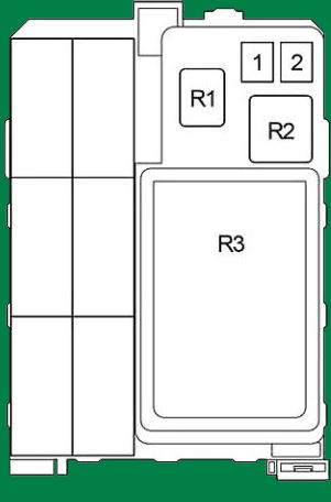
| Back side | ||
|
||
| 1 | Rear differential lock system, ABS, TRC, VSC, fuses: "ACC", "CIG", "ECU-IG & GAUGE", "WIP" | 40 |
| 2 | Fuses: "PWR", "S-HTR", "4WD", "DOOR", "DEF", "MIR HTR" | 40 |
| Relay | ||
| R1 | Sockets | |
| R2 | Heater | |
| R3 | Integrated relay | |
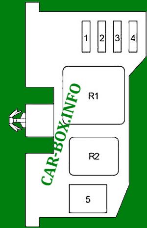
Relay box #11
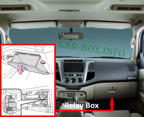
Located behind the glove compartment.
| Diagram | ||
|---|---|---|
|
||
| No. | Protected chain | A |
| 1 | Central locking, power windows | 25 |
| 2 | Heated rear window, multiport fuel injection system / sequential multiport fuel injection system | 20 |
| 3 | Empty | - |
| 4 | Rear differential lock system, ABS, TRC, VSC | 20 |
| 5 | Power Windows | 30 |
| Relay | ||
| R1 | Ignition | |
| R2 | Heated rear window | |
Car body
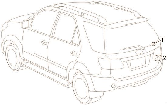
Location of components:
- Rear heater relay;
- Parktronic control unit
