Sales of the second generation Toyota Highlander in the United States started in 2007. While maintaining the general style, the car received a different plastic of the body sidewalls, but with the same developed wheel arches, the slope of the roof became slightly more pronounced, the headlights became narrower and elongated, the front part became more streamlined. The body of the new car has become larger in general, and the interior is more spacious. The Highlander is more comfortable and safer than its predecessor, thanks to new options and technical improvements. Three options were offered for the units. This is a 2.7-liter "four" 1AR-FE (187 hp), a 3.5-liter V6 (2GR-FE, 270 hp) and a hybrid gasoline-electric unit based on a 3.3-liter V6 (3MZ-FE, 209 hp).
Considered fuse diagrams relevant for Toyota Highlander (U40) models 2007, 2008, 2009, 2010, 2011, 2012, 2013, 2014 release.
In the passenger compartment
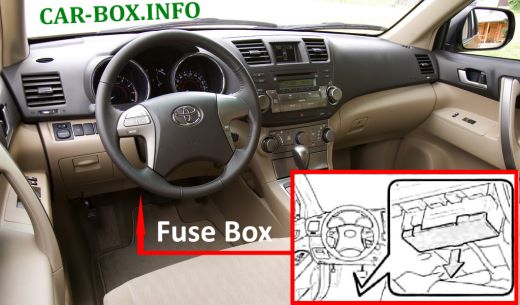
Fuse box located on the driver's side, at the bottom of the dashboard.
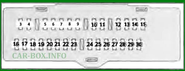
General view.
| Diagram | ||
|---|---|---|
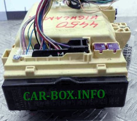
front side |
||

on the back of the block cover |
||
| No. | A | Description |
| 1 | 30 | Power front seats |
| 2 | 30 | Power windows |
| 3 | 25 | Power window, rear right door |
| 4 | 25 | Power window, rear left door |
| 5 | 15 | Fog lamps |
| 6 | 7.5 | Self-diagnosis system |
| 7 | 25 | Windshield wiper de-icer |
| 8 | 10 | Signal table, VSC system |
| 9 | 25 | Power windows |
| 10 | 7.5 | Launch system |
| 11 | 7.5 | Not used |
| 12 | 7.5 | Not used |
| 13 | 30 | Electric sunroof |
| 14 | 15 | Tail lamps, license plate lights, fog lights, trailer lighting |
| 15 | 7.5 | Glove box illumination, alarm, radio, side mirror heater, clock, central locking, front seat heaters, audio and video system for rear passengers, VSC system, instrument cluster illumination rheostat, automatic transmission control system, descent assist system, steering switches wheel |
| 16 | 10 | Mnltinlpx system, electric sunroof, automatic transmission control system, electric rear door, heated front seats, tire pressure monitoring system, electric steering column |
| 17 | 7.5 | VSC system |
| 18 | 10 | Air conditioning |
| 19 | 20 | Windshield wiper and washer |
| 20 | 20 | Heated front seats |
| 21 | 10 | Radio, heated side mirrors, reversing lights, charging system, hazard warning lights, TRC system, rheostat for dimming the instrument cluster illumination, defroster for windshield wipers |
| 22 | 30 | Windshield wiper and washer |
| 23 | 15 | Rear door glass cleaner and washer |
| 24 | 10 | Fuel injection system, steering wheel lock system, ABS system, SRS system, Entry Start system |
| 25 | 7.5 | Gauges and indicators, rear view camera |
| 26 | 7.5 | Interior rearview mirror, automatic transmission selector locking system. system "Entrv & Start" |
| 27 | 10 | Connector for additional equipment |
| 28 | 20 | Connector for additional equipment |
| 29 | 7.5 | Radio tape recorder, clock, audio, video system for rear passengers, charging system, interior lighting |
| 30 | 15 | Heated side mirrors |
In the engine compartment
Fuse box #1
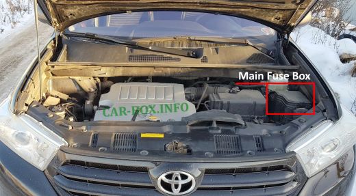
Located on the right side of the engine compartment.

General form.
| Assigment of fuses in the passenger compartment box #1 | ||
|---|---|---|

back side |
||
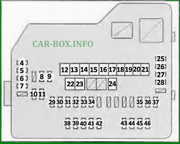
front side |
||
| No. | Decoding | A |
| 1 | Spare | 7.5 |
| 2 | 15 | |
| 3 | 25 | |
| 4 | Rear door glass heater | 10 |
| 5 | MIR HTR (15 A) | 20 |
| 6 | Connector for additional equipment | 20 |
| 7 | "Multiplex" system | 25 |
| 8 | EFI injection system No. 2 | 10 |
| 9 | EFI injection system No. 3 | 10 |
| 10 | INJ starting system No. 1 | 15 |
| 11 | INJ starting system No. 2 | 10 |
| 12 | Air conditioning | 50 |
| 13 | ABS system | 50 |
| 14 | Cooling system radiator fan | 50 |
| 15 | ABS system | 30 |
| 16 | Not used | 50 |
| 17 | 30 | |
| 18 | 30 | |
| 19 | Air conditioning | 40 |
| 20 | Rear door glass heater | 30 |
| 21 | Rear door electric drive | 30 |
| 22 | Fuses "MIR HTR", "P / OUT". DOOR 1, HTR, RR DEF. "FAN MAIN". "ABS number 1". "PTC N91", "RR CLR" "PTC # 2". "PTC # 3", "ABS # 2". "PBD" | 140 |
| 23 | Electric power steering | 80 |
| 24 | ST start system | 30 |
| 25 | Audio and video system for rear passengers | 10 |
| 26 | Radio cassette | 15 |
| 27 | Steering wheel position sensor. gauges and indicators, clock, air conditioner, body electrical control unit, central locking remote control system, "Entry & Start" system, rear door electric drive, self-diagnosis system | 10 |
| 28 | Interior lighting, gauges and indicators, electric tailgate | 10 |
| 29 | Radio cassette | 15 |
| 30 | Trailer lamps | 30 |
| 31 | Fuses "INJ No. 1", "INJ No. 2" | 25 |
| 32 | Steering wheel lock system | 20 |
| 33 | Fuses "EFI No. 2". "EFI No. 3" | 25 |
| 34 | Direction indicators | 15 |
| 35 | Central locking system "Multiplex" | 10 |
| 36 | Charging system | 7.5 |
| 37 | Multiplex system | 7.5 |
| 38 | Left headlamp (high beam) | 15 |
| 39 | Right headlamp (high beam) | 15 |
| 40 | Left headlamp (low beam) | 15 |
| 41 | Right headlamp (low beam) | 15 |
| 42 | Horn | 10 |
| 43 | Injection system, "Entry & Start" system | 10 |
| 44 | Injection system, throttle control system | 10 |
| 45 | Air fuel ratio sensor | 20 |
| 46 | Horn | 7.5 |
Fuse box #2
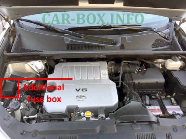
Location.
| Diagram | ||
|---|---|---|
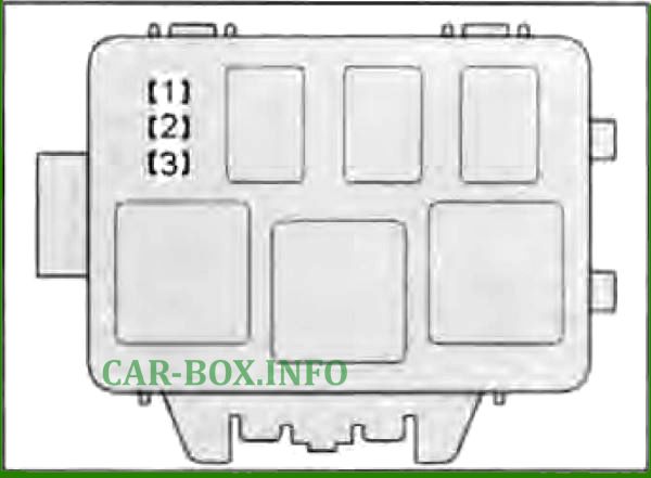
|
||
| No. | Protected chain | A |
| 1 | INV-W / P Not used | 15 |
| 2 | IGCT # 2 Not used | 7.5 |
| 3 | A / CD Not used | 10 |
