The Highlander / Kluger family is built on the Toyota K platform, which is common with the Camry sedan and some of the company's other models - in particular, the first generation Highlander shares it with its relative Lexus RX / Toyota Harrier. The car belongs to the class of mid-size crossovers. In this article, we will take a detailed look at the fuse diagrams for the the Toyota Highlander / Kluger V 1st generation (XU20): 2000, 2002, 2003, 2004, 2005, 2006, 2007 release.

Here you will find the locations and photos of distribution boxes. Separately, we note the fuse responsible for the cigarette lighter and the fuel pump relay.
In the engine compartment
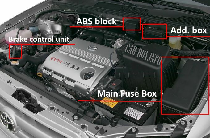
The main box is located next to the battery, above it there are two additional ones, one of which is responsible for the ABS system, and the second for the daytime running lights.
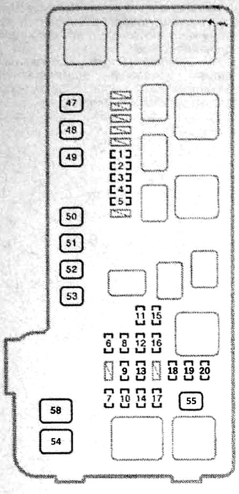
Fuse box #1
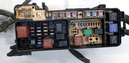
General view.
| Diagram | ||
|---|---|---|
|
||
| No. | Protected circuit | A |
| 1 | Starter | 7.5 |
| 2 | ABS / TRAC / VSC systems | 7.5 |
| 3 | Right healamp (low beam) | 15 |
| 4 | Left healamp (low beam) | 15 |
| 5 | Fuel Ratio Sensors | 25 |
| 6 | Generator | 7.5 |
| 7 | Trailer electrical equipment | 20 |
| 8 | Horn | 10 |
| 9 | Immobilizer system | 15 |
| 10 | Right headlight (high beam) | 10 |
| 11 | Anti-theft system, remote control door locks, central locking, ABS / TRAC / VSC systems, air conditioning, instruments | 7.5 |
| 12 | Electronic engine control unit, fuel injection system, fuel pump, immobilizer system | 20 |
| 13 | Immobilizer system, central locking | 25 |
| 14 | Left headlamp (high beam) | 10 |
| 15 | Audio system | 25 |
| 16 | Interior lighting, spot lighting. luggage compartment lighting, illuminated vanity mirror, ignition switch lighting, door remote control system | 10 |
| 17 | Alarm | 15 |
| 18 | Spare | 7.5 |
| 19 | Spare | 15 |
| 20 | Spare | 25 |
| 47 | Fuel injection system, starter | 30 |
| 48 | ABS electric pump | 40 |
| 49 | Э / М ABS system valves | 40 |
| 50 | Air conditioner and heater | 50 |
| 51 | Radiator fan | 30 |
| 52 | Heated rear window | 30 |
| 53 | Condenser fan | 30 |
| 54 | Spare RDI | 50 |
| 55 | Fuse circuits "HEAD LP RH LWR", "HEAD LP LH LWR". "HEAD LP RH UPR", "HEAD LP LH UPR" | 40 |
| 58 | Fuse circuits "ABS1", "ABS2", "RDI", "CDS", "RR DEF", "HEATER", "AM1", "AM2". "TAIL". "PANEL", "STOP". "S / ROOF". "SEAT HTR" | 140 |
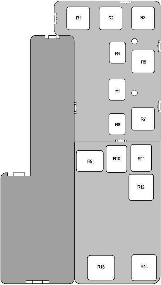
| Purpose of the relay modules in the main block | |
|
|
| No. | Description |
| R1 | Cooling fan (FAN1) |
| R2 | Starter |
| R3 | Cooling fan (FAN3) |
| R4 | Air Fuel Ratio (A / F) Sensor |
| R5 | Inverter |
| R6 | Empty |
| R7 | Cooling fan (FAN2) |
| R8 | Empty |
| R9 | A / C Compressor Clutch (MG CLT) |
| R10 | Horn |
| R11 | Engine control unit (EFI) |
| R12 | Heated rear window |
| R13 | Headlights (HEAD LAMP) |
| R14 | Empty |
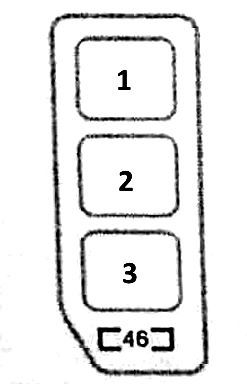
Fuse box #2
Description of the additional block in the engine bay.
| Diagram. | ||
|---|---|---|
|
||
| 46 | DRL - Daytime Running Lamp | 7.5 |
| 1 | Daytime running lamp relay | - |
| 2 | - | |
| 3 | - | |
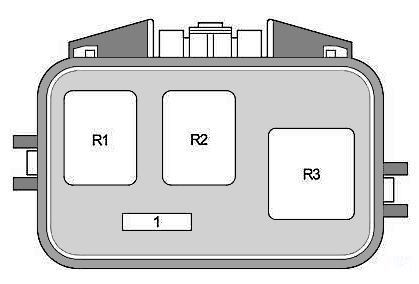
ABS block
Diagram.
|
|
| 1 | Empty |
| R1 R2 R3 |
anti-lock braking system (ABS) |
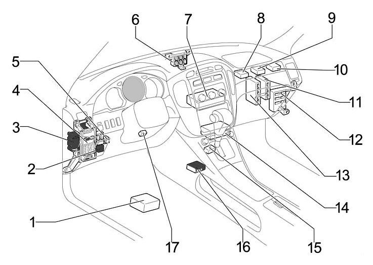
In the passenger compartment
General layout of the electronic components.
|
|
| No. | Component |
| 1 | Navigation control module |
| 2 | Heater relay |
| 3 | Cabin relay box |
| 4 | Cabin fuse box |
| 5 | Turn signal relay (alarm) |
| 6 | Distribution block |
| 7 | Air conditioning control module (without navigation) |
| 8 | Anti-theft control module |
| 9 | Network gateway module |
| 10 | Key transponder computer |
| 11 | Body ECM |
| 12 | Distribution block |
| 13 | Engine control module |
| 14 | Air conditioning control module (if navigation is available) |
| 15 | Gear selector lock module |
| 16 | Central airbag unit |
| 17 | Key transponder amplifier |
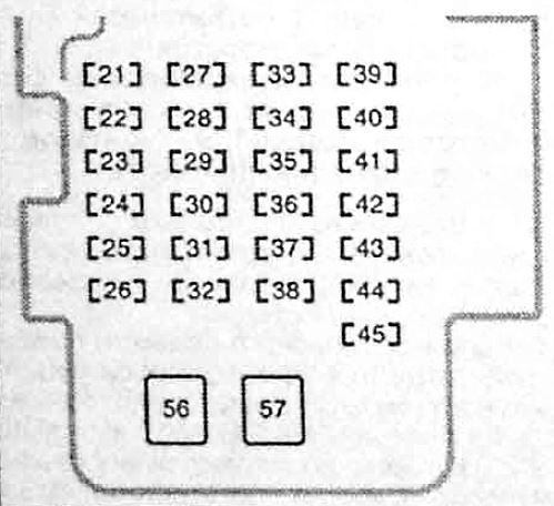
Fuse box
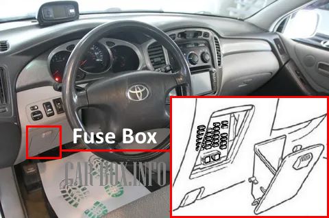
Located under the dashboard. Next to it there is also a cabin relay box.

General view.
| Diagram | ||
|---|---|---|
|
||
| No. | Description | A |
| 21 | Instruments, switches and switches, SRS system | 7.5 |
| 22 | Audio system | 7.5 |
| 23 | Highlander / Kluger cigarette lighter fuse | 15 |
| 24 | Power windows for rear doors | 20 |
| 25 | Socket for connecting additional equipment | 15 |
| 26 | Front fog lamps | 15 |
| 27 | Airbag System (SRS) | 15 |
| 28 | ABS / TRAC / VSC systems, cruise control system, electric sunroof, automatic transmission selector lock system, alarm, charging system, starter | 15 |
| 29 | Windshield wiper | 25 |
| 30 | Power windows for rear doors | 20 |
| 31 | Power windows for front doors, door lights, central locking | 25 |
| 32 | electric sunroof | 20 |
| 33 | Air conditioning and heater. rear door glass heater, side mirror heater, cooling fan | 15 |
| 34 | Remote control door locks, central locking, heated side mirrors, ABS / TRAC / VSC systems. fuel injection system, reversing light | 7.5 |
| 35 | Rear door glass wiper | 15 |
| 36 | Stop lights, additional stop lights. ABS / TRAC / VSC systems. cruise control system, automatic transmission selector lock system, fuel injection system | 20 |
| 37 | Engine self-diagnosis system. Automatic transmission, ABS / TRAC / VSC systems. SRS systems | 7.5 |
| 38 | Front seat heaters | 15 |
| 39 | Fuel injection system, charging system, starter | 15 |
| 40 | Windshield Washer Fluid Low Level Indicator | 20 |
| 41 | Spare or RR FOG - Rear Fog Lights | 7.5 |
| 42 | Air conditioning, heated side mirrors | 20 |
| 43 | Power windows (front doors) | 25 |
| 44 | Front and rear parking lamps, license plate lamps, switch and switch lamps, fog lamps, turn signal repeaters (flasher) | 10 |
| 45 | Illumination of switches and switches | 7.5 |
| 56 | Fuel injection system, starter | 40 |
| 57 | Power seat adjustment | 30 |
| Relay modules on the back of the unit | ||

|
||
| R1 | Tail lamps | |
| R2 | Fog lamps | |
| R3 | Auxiliary (ACC) | |
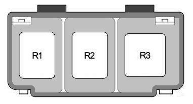
Relay box
Diagram.
|
|
| No. | Decoding |
| R1 | Toyota Highlander / Kluger Fuel Pump Relay (Circuit Opening) |
| R2 | Heated seats |
| R3 | Heating of the rest zone of the brushes |
Car body electrical equipment
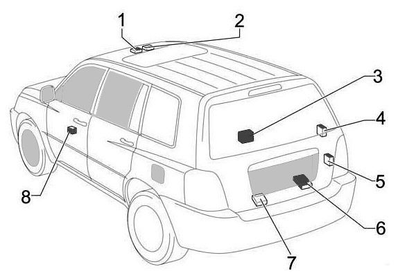
Location of components 1. Sunroof control module, 2. Junction block, 3. Multimedia system control module for rear passengers (without rear heater), 4. Central locking control module, 5. Rear heater relay, 6. Audio amplifier, 7. Module multimedia system control for rear passengers, 8. Power window control module
