Toyota Celica is a stylish car model that appeared during the boom of RV (recreational vehicle). At that time, few machines were produced specifically for young people, therefore, in order to stop this trend, a new (at that time) generation was created. In this article, we will take a detailed look at the fuse box diagrams for the 6th generation Toyota Celica (T200: ST201, ST202, ST203, ST204, ST205) 1993, 1994, 1995, 1996, 1997, 1998, 1999 release. The information is also suitable for the Carina ED and Exiv models of the same release period, since they have a similar platform.
Here you will find the locations and photos of distribution boxes. The fuses responsible for the “Cigarette lighter” and “Fuel Pump” are highlighted in bold.
In the engine compartment
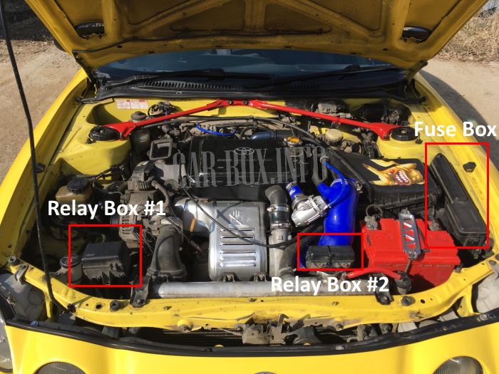
The engine compartment contains one main fuse box and two unit relays.
Fuse box
An example of access to the main block.
| Diagram | ||
|---|---|---|
|
||
| No. | Description | A |
| 1 | Start system AM2 | 30 |
| 2 | Emergency flashers - HAZARD | 10 |
| 3 | HORN - Sound Signal | 7.5 |
| 4 | RADIO No.1 - Car audio system | 20 |
| 5 | ECU-B - Anti-lock braking system, cruise control | 15 |
| 6 | DOME - Interior lamps, personal lamps, luggage compartment lamps, door lamps, clock | 10 |
| 7 | Left Headlamp - HEAD (LH) | 15 |
| 8 | Right Headlamp - HEAD (RH) | 15 |
| 9 | Empty | - |
| 10 | - | |
| 11 | - | |
| 12 | Charging system | 7.5 |
| 13 | SRS airbag warning lamp | 7.5 |
| 14 | sequential multiport fuel injection system - EFI | 15 |
| 15 | Left Headlamp (low beam) - HEAD (LH) LO | 15 |
| 16 | Right Headlamp (low beam) - HEAD (RH) LO | 15 |
| 17 | Right Headlamp (high beam) - HEAD-HI (RH) | 15 |
| 18 | Left Headlamp (high beam) - HEAD-HI (LH) | 15 |
| 19 | DRL - Daytime Running Lamps System | 7.5 |
| 36 | cooling fan RDI | 30 |
| 37 | cooling fan CDS | 30 |
| 42 | Conditioner HTR | 40 |
| 43 | ALT - Fuses "ALT-S", "TAIL", "DOOR", "DEF" and "POWER" | 100 |
| 44 | MAIN - Starting system, headlights, fuses "AM2", "HAZARD", "HORN", "DOME" and "RADIO". | 60 |
| 45 | ABS - Anti lock brake system | 50 |
| R1 | Radiator fan relay 1 | |
| R2 | Main motor relay | |
| R3 | Horn relay | |
| R4 | Headlamps | |
| R5 | Starter | |
| R6 | Injection system | |
Relay block #1
Diagram.
|
|
| R1 | 4WS main motor relay |
| R2 | - |
| R3 | 4WS main motor relay |
Relay block #2
Diagram.
|
|
| R1 | ABS solenoid valve |
| R2 | 2 radiator fan motor |
| R3 | ABS electric pump |
| R4 | 2 radiator fan motor |
| R5 | air conditioning compressor electromagnetic clutch |
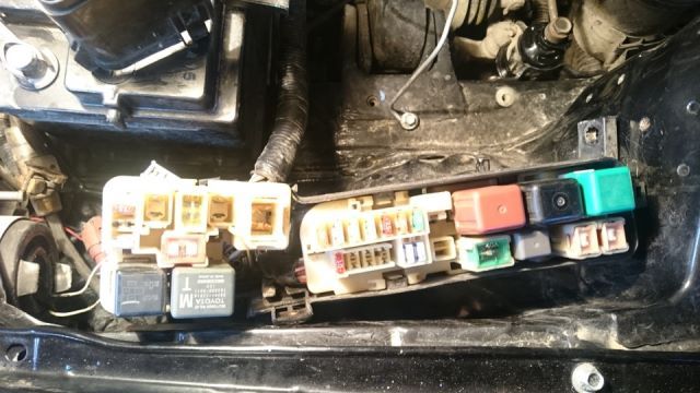
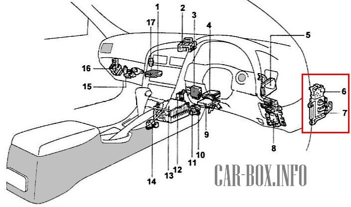
In the passenger compartment
General layout of the electrical equipment.
|
|
| 1 | air conditioner amplifier |
| 2 | JC # 3 |
| 3 | central lock control relay |
| 4 | electronic air conditioner control module |
| 5 | electronic ABS control module |
| 6 | relay box 1 |
| 7 | fuse block 1 |
| 8 | fuse block under the dashboard |
| 9 | electronic engine control module |
| 10 | fuel pump relay toyota selica / karina ed |
| 11 | deceleration sensor |
| 12 | the main relay of the electric drive of the roof folding |
| 13 | audio amplifier |
| 14 | start inhibit switch |
| 15 | relay block No. 4 |
| 16 | mirror control relay |
| 17 | mode relay "EX-HI" |
Fuse box
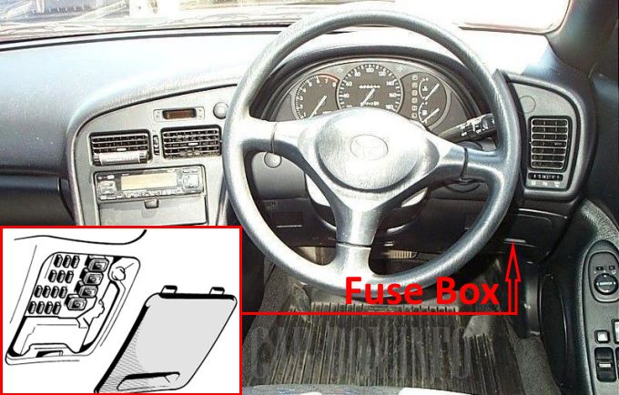
Located behind the plastic cover on the driver's side, next to it (just above) is the relay box.
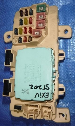
General view.
| Diagram | ||
|---|---|---|
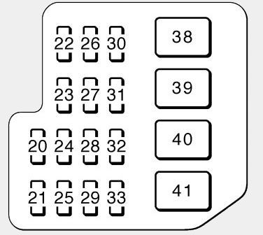
|
||
| No. | Decoding | A |
| 20 | ECU-IG - electronically controlled automatic transmission, anti-lock braking system ABS | 15 |
| 21 | SEAT-HTR - Heated seats | 20 |
| 22 | PANEL - Instrument panel light | 7.5 |
| 23 | STOP - Stop lights, stop light high, sequential multiport fuel injection, cruise control override, electronically controlled automatic transmission, anti-lock braking system | 15 |
| 24 | Front fog lamps (FOG) | 20 |
| 25 | Toyota celica 200 cigarette lighter fuse, digital clock display, car audio system | 15 |
| 26 | Charging system, warning lamps, sequential multiport fuel injection system, SRS airbag system | 7.5 |
| 27 | WIPER - Windshield and rear window wipers and washer, | 20 |
| 28 | MIR-HTR - sequential multiport fuel injection system | 10 |
| 29 | TURN - Turn signal, emergency flashers | 10 |
| 30 | Tail lights, parking lights, front side marker lights, rear side marker lights, license plate lights (TAIL) | 15 |
| 31 | HTR - Air conditioning system, heated rear window | 10 |
| 32 | Gauges & Counters, Power Door Lock System (GAUGE) | 10 |
| 33 | Starting system, sequential multiport fuel injection system | 7.5 |
| 34 | Air conditioner A / C | 10 |
| 35 | OBD II On-Board Diagnostic System | 7.5 |
| 38 | AM1 - Electronic ignition system / distribution ignition system | 40 |
| 39 | DOOR - Power door locking system, convertible top control system | 30 |
| 40 | DEF - Heated rear window | 30 |
| 41 | POWER - Power windows, power sunroof | 30 |
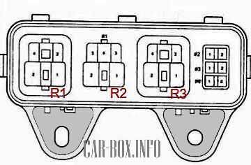
| Relay modules on the back of the unit | ||

|
||
| R1 | Tail lamps | |
| R2 | power relay | |
| R3 | rear window heater | |
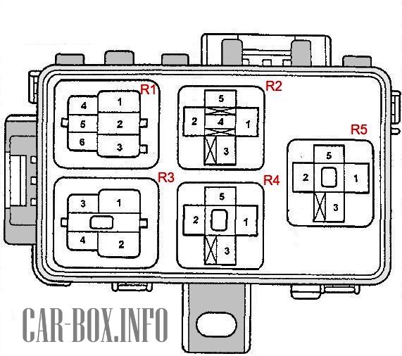
Relay box
No. 6 on the picture.
| Diagram | |
|---|---|

|
|
| R1 | Relay - turn signal interrupter |
| R2 | Empty |
| R3 | Fog lamp relay |
| R4 | Empty |

Do you have any information on 1995 Celica top stack relays, especially the Top Stack Relay and the Top Stack Main Relay?