Unveiled at the January 1999 Detroit Auto Show, the XYR concept car was created at Toyota's Calty Design studio in California. The XYR is the seventh, more stylish generation of the Toyota Celica, born in an atmosphere of changing auto sales market. In this article, we will take a detailed look at the fuse box diagrams for the 7th generation Toyota Celica (T230) 1999, 2000, 2001, 2002, 2003, 2004, 2005, 2006 release.
Here you will find the locations and photos of distribution boxes. The fuses responsible for the “Cigarette lighter” and “Fuel Pump” are highlighted in bold.
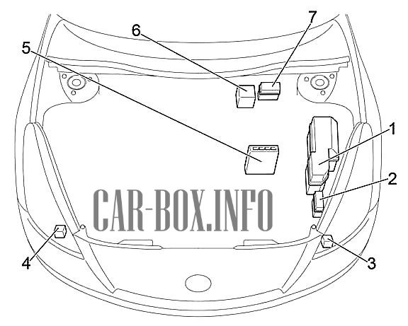
In the engine compartment
General diagram of the electrical equipment.
|
|
| 1 | Fuse box |
| 2 | Relay box #1 |
| 3 | '02 -'06: Air Pump Relay |
| 4 | '02 -'06: Headlamp Washer Relay |
| 5 | Engine control module (M / T) or engine and transmission control module (A / T) |
| 6 | '02 -'06: ABS & TRC & VSC (with VSC) |
| 7 | Vehicle stability control module (without VSC) |
| 8 | '02 -'06: Relay Box # 2 |
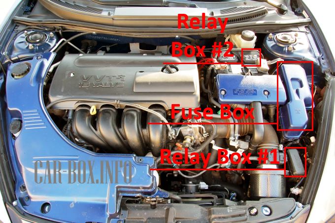
Under the hood is one main fuse box and two additional relay boxes. The second relay block has been installed on cars since 2002.
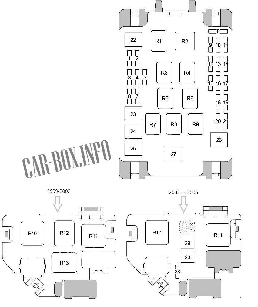
Main fuse box
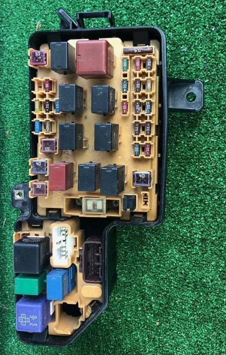
Photo - an example of the execution of the main unit.
| Diagram | ||
|---|---|---|
|
||
| No. | Description | A |
| 1 | S-HTR - '02 -'05: Heated seats | 20 |
| AUTO ANTENNA - USA: Antenna | 15 | |
| 2 | HEAD LH UPR - High beam left Headlamp | 10 |
| 3 | HEAD RH UPR - High beam right Headlamp (HEAD RH UPR DRL2) | 20 |
| 4 | HEAD LVL - Daytime running lamp, Headlamp range control unit | 7.5 |
| DRL3 - Daytime running lights | 7.5 | |
| 5 | '99 -'02: Low Beam Right Headlamp | 10 |
| '02 -'06: Low beam right Headlamp | 15 | |
| 6 | '99 -'02: Low beam left Headlamp | 10 |
| '02 -'06: Low beam left Headlamp | 15 | |
| 7 | ABS system | 25 |
| 8 | Empty | - |
| 9 | Empty | - |
| 10 | Horn | 10 |
| 11 | ALT-S - Charging system | 7.5 |
| 12 | Empty | |
| 13 | EFI1 - sequential multiport fuel injection system | 10 |
| EFI1 - sequential multiport fuel injection system | 7.5 | |
| 14 | DCC - Fuses: "RADIO", "DOME", "MPX-B", "ECU-B" | 25 |
| 15 | Empty | |
| 16 | EFI2 - sequential multiport fuel injection system | 7.5 |
| 10 | ||
| 17 | EFI - sequential multiport fuel injection system, fuses: "EFI1", "EFI2" | 20 |
| EFI - Europe 2ZZ-GE: sequential multiport fuel injection system, fuses: "EFI1", "EFI2" | 15 | |
| 18 | ST - Starting system, sequential multiport fuel injection system | 7.5 |
| 19 | AM2 - Starting system | 7.5 |
| 20 | IG2 - Starting system, sequential multiport fuel injection system | 15 |
| 21 | HAZ hazard warning lights and direction indicators | 15 |
| Australia, USA : HAZ hazard warning lights and direction indicators | 10 | |
| 22 | HTR - Air conditioner / heater | 50 |
| 23 | Engine cooling fan RDI | 30 |
| 24 | '99 -'02: ABS system | 40 |
| '02 -'06: ABS System | 50 | |
| 25 | Engine cooling fan CDS | 30 |
| 26 | MAIN - Starting system, daytime running lights, fuse: "ST" | 40 |
| MAIN - Europe 2ZZ-GE: Starting system, daytime running lights, fuse: "ST" | 50 | |
| 27 | ALT - Cooling system, engine cooling fan, starting system, rear window heating, side light, fuses: "ABS NO.1", "ABS NO.2", "HTR", "FR P / W", "FL P / W ”,“ DOOR ”,“ OBD ”,“ STOP ”,“ S / ROOF ”,“ MIR HTR ”,“ FR FOG ”,“ AM1 ” | 120 |
| 28 | Throttle body ETCS | 10 |
| 29 | Air pump A-PMP | 50 |
| 30 | CLN H-LP - Headlight washers | 30/50 |
| Purpose of relay modules | ||
| R1 | Horn | |
| R2 | Headlamps (HEAD) | |
| R3 | Toyota Celica Fuel Pump Relay (C / OPN) | |
| R4 | Engine control unit (EFI) | |
| R5 | Engine cooling fan (FAN1) | |
| R6 | Ignition (IG2) | |
| R7 | Engine cooling fan (FAN2 / FAN3) | |
| R8 | ||
| R9 | A / C compressor relay (MG / C) | |
| R10 | Starter (ST) | |
| R11 | Heater (HTR) | |
| R12 | ABS SOL | |
| R13 | ABS motor | |
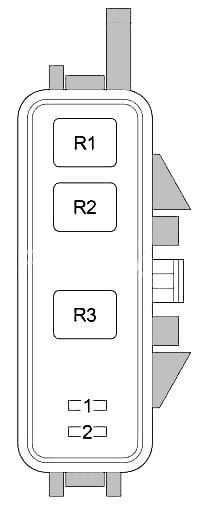
Relay blocks
Diagrams.
| Block #1 | |
|
|
| R1 | Daytime Running Lamps |
| R2 | |
| R3 | Daytime running Lamps(DRL2 - DIMMER) |
| 1 | High beam - left 10A |
| 2 | High beam - right, daytime running lamps 10A |
| Block #2 (2002 - 2006) | |
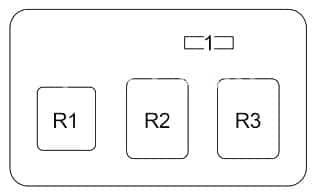
|
|
| 1 | VSC - 10A |
| R1 | VSC MTR |
| R2 | MTR CUT |
| R3 | VSC SOL |
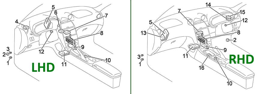
In the passenger compartment
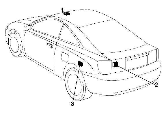
General diagram of the electrical equipment.
|
|
| 1 | Rear fog lamp relay |
| 2 | Hazard and turn signal lamps relays |
| 3 | Front fog lamp relay |
| 4 | '02 -'06: Headlamp leveling control module |
| 5 | '02 -'06: Vehicle stability control module |
| 6 | '99 -'02 (LHD): ABS Control Module |
| 7 | Air conditioner control module |
| 8 | Fuse box |
| 9 | Body ECU |
| 10 | '02 -'06: Heated Seat Relay |
| 11 | Airbag control module |
| 12 | Key transponder amplifier |
| 13 | '02 -'06 (Australia): Headlight range control module |
| '99 -'02 (RHD): ABS Control Module | |
| 14 | 14. '02 -'06 (RHD): Headlight range control module |
| 15 | 15. '02 -'06 (Australia): Cruise Control Module |
| 16 | 16. '02 -'06 (Australia): Gear selector lock control module |
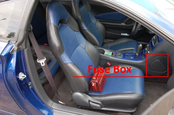
Located on the passenger side (left-hand drive models), or on the driver's side (right-hand drive models), at the bottom left behind the protective cover.
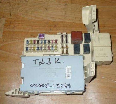
General view of the distribution box.
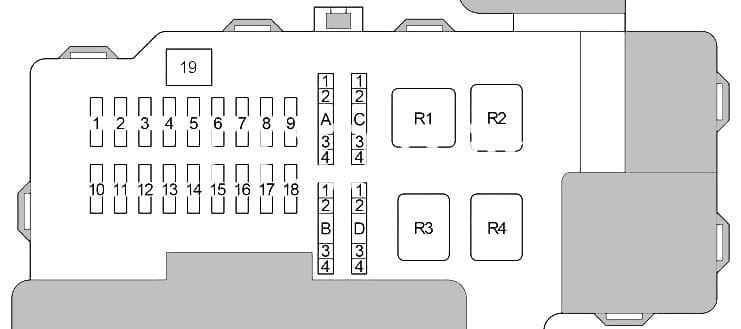
| Toyota Celica T230 interior fuse box diagram | ||
|---|---|---|
|
||
| No. | Description | A |
| 1 | Sunroof (S / ROOF) | 15 |
| 2 | Power windows (FL P / W) | 20 |
| 3 | Stop lamps, ABS, auxiliary brake lamp, multiport fuel injection system / sequential multiport fuel injection system, automatic transmission control unit, cruise control (STOP) | 10 |
| 4 | Airbags (SRS-IG) | 7.5 |
| 5 | Windshield washer, rear window washer (WASHER) | 15 |
| 6 | Audio system (RADIO) | 15 |
| 7 | Direction indicators (TURN) | 7.5 |
| 8 | Air conditioner (HTR) | 10 |
| 9 | Parking Lamps, Instrument Panel Lights, License Plate Lights (TAIL) | 10 |
| 10 | CIG - Toyota Celica Cigarette Lighter Fuse (T23) | 15 |
| 11 | AM1 - Starting system, fuses: "CIG", "ECU ACC", "SRS − IG", "WASHER", "WIPER", "BK / UP LP", "TENS RDC", "DEF RLY", "BODY ECU −IG "," TURN "," HTR "," WARNING "," FAN RLY "," ABS − IG "," ECU − IG " | 25 |
| 12 | DOOR - Central locking | 20 |
| 13 | Front fog lamps (FR FOG) | 15 |
| 14 | OBD diagnostic connector | 7.5 |
| 15 | Front wiper | 25 |
| 16 | MIR HTR - Heated mirrors | 10 |
| 17 | Rear wiper - RR WIPER | 15 |
| 18 | FR P / W - Power Windows | 20 |
| 19 | Heated rear window (DEF) | 30 |
| A line | ||
| 1 | MPX-B - Remote door lock control system | 7.5 |
| 2 | Rear fog lamps (RR FOG) | 7.5 |
| 3 | Clock, interior lamps (DOME) | 7.5 |
| 4 | Air conditioning, instrument cluster (ECU-B) | 7.5 |
| B line | ||
| 1 | Charging system, instrument cluster (WARNING) | 5 |
| 2 | Cruise control (ECU-IG) | 5 |
| 3 | ABS-IG - ABS system | 5 |
| 4 | Engine cooling fan (FAN RLY) | 5 |
| C line | ||
| 1 | Glove compartment lighting, instrument panel lighting (PANEL 1) | 7.5 |
| 2 | Front fog lamps, instrument cluster illumination (PANEL 2) | 7.5 |
| 3 | Clock, audio system, mirror control module, antenna (ECU-ACC) | 7.5 |
| 4 | Empty | - |
| D line | ||
| 1 | Reversing lamps (BK / UP LP) | 5 |
| 2 | Heated rear window, heated mirrors (DEF RLY) | 5 |
| 3 | Multiplex module (BODY ECU-IG) | 5 |
| 4 | TENS RDC - Automatic Transmission Control Module, Transmission Selector Lock, Sunroof, Aerial | 5 |
| Purpose of relay modules | ||
| R1 | Ignition (IG1) | |
| R2 | Tail lamps (TAIL) | |
| R3 | Heated mirrors (MIR HTR) / heater | |
| R4 | Heated rear window (DEF) | |
Car body
Location of components:
- Sunroof relay (if equipped),
- Rear wiper relay,
- Central locking receiver
