
Table of Contents
Most vehicle electrical circuits are protected by fuses. High-draw electrical loads are connected via relays. Fuses and relays are housed in power distribution boxes: one is located in the passenger compartment beneath the lower instrument panel, and the other is in the engine compartment.

This information applies to 1st-generation Geely MK and MK Cross models (2006–2016).
Passenger Compartment Fuse Box
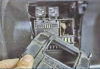
To access the interior fuse and relay distribution box, carefully unclip and remove the cover.
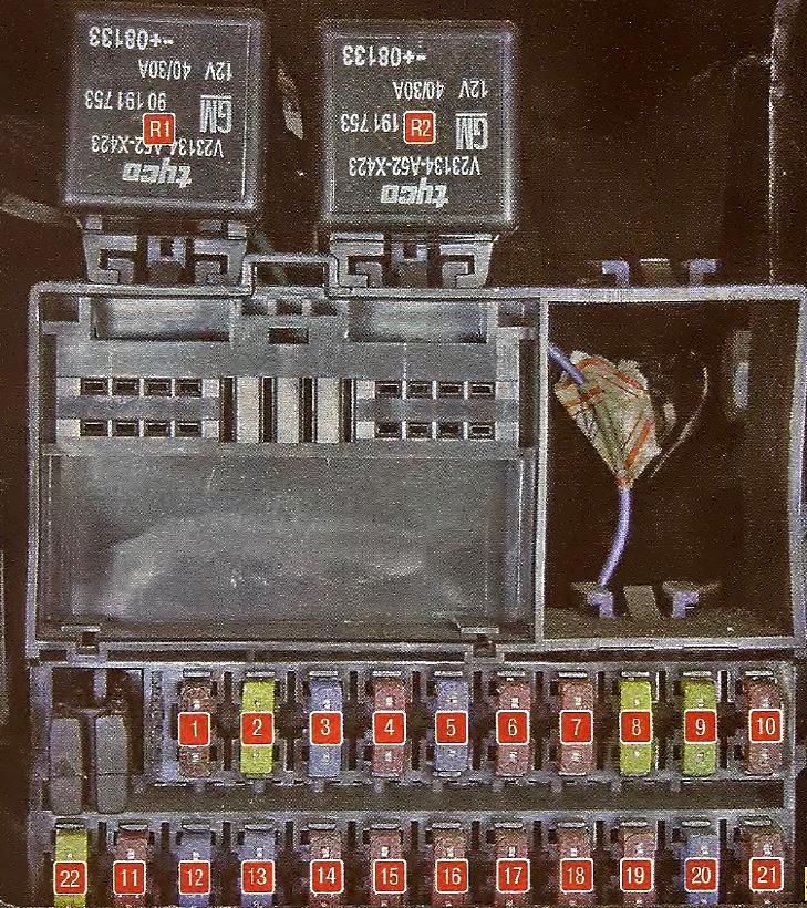
| Diagram | ||
|---|---|---|
|
||
| No. (A) | Label | Protected Circuit / Function |
| Standard Fuses | ||
| 1 (7.5) | A/C | Air conditioning system |
| 2 (20) | POWER | Main power supply |
| 3 (15) | TAIL | Tail lamps |
| 4 (10) | STOPLP | Brake lamps |
| 5 (15) | HAZARD | Hazard warning lights |
| 6 (10) | ENG ECU | Engine Control Unit (ECU) |
| 7 (10) | REMOTE | Remote keyless entry system |
| 8 (20) | RR DEF | Rear window defogger |
| 9 (20) | DR LOCK | Central door locking system |
| 10 (10) | ROOMLP | Interior dome light |
| 11 (10) | MIR | Power side mirrors |
| 12 (15) | CIGAR LIGHTER | Cigarette lighter / 12V power outlet |
| 13 (15) | IGN COIL | Ignition coil assembly |
| 14 (10) | SRS ECU | Supplemental Restraint System (SRS) airbag module |
| 15 (10) | REMOTE | Remote keyless entry system |
| 16 (10) | B/UP | Reverse lamps |
| 17 (10) | ABS ECU | ABS hydraulic control module |
| 18 (10) | PHONE | Audio system / Hands-free interface |
| 19 (10) | ALT | Alternator voltage sense |
| 20 (15) | WIPER | Windshield wipers |
| 21 (10) | CLUSTER | Instrument cluster |
| - | - | Spare |
| Relays | ||
| R1 | TAIL | Tail lamps relay |
| R2 | BLOWER | Blower motor relay |
Engine Compartment Fuse Box
Power Distribution Box
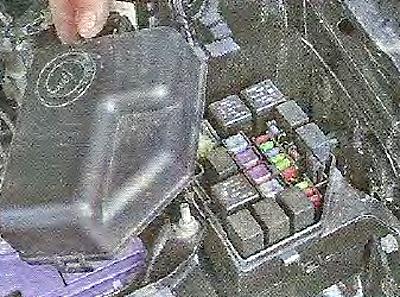
To access the engine compartment power distribution box, open the hood, press the release cover latch, and remove the cover.
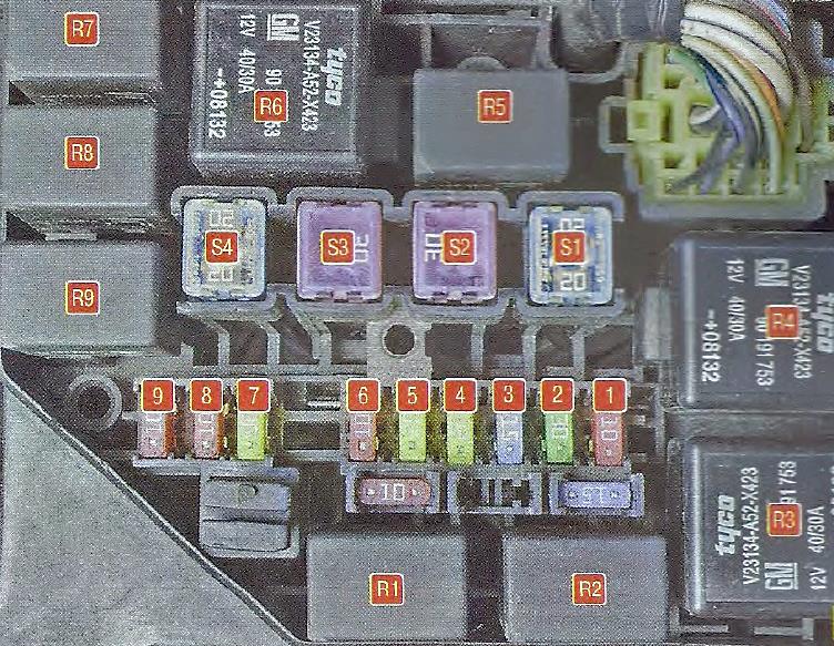
| Diagram | ||
|---|---|---|
|
||
| No. (A) | Label | Protected Circuit / Function |
| Standard Fuses | ||
| 1 (10) | A/COM | A/C compressor magnetic clutch |
| 2 (30) | STA | Starter solenoid circuit |
| 3 (15) | FRTF0G | Front fog lamps |
| 4 (20) | CON FAN | A/C condenser cooling fan |
| 5 (20) | RAD FAN | Radiator cooling fan |
| 6 (10) | HORN | Horn |
| 7 (20) | MAIN | Main engine control relay |
| 8 (10) | H-LP RH | Right headlamp assembly |
| 9 (10) | H-LPLH | Left headlamp assembly |
| High-Current Fuses (Maxi Fuses) | ||
| S1 (20) | AM2 | Ignition switch (Circuit 2) |
| S2 (30) | AM1 | Ignition switch (Circuit 1) |
| S3 (30) | P/WDW | Power windows |
| S4 (20) | BLOWER | Climate blower motor |
| Relays | ||
| R1 | RAD FAN | Radiator fan relay |
| R2 | CON FAN | Condenser fan relay |
| R3 | STA | Starter relay |
| R4 | FRT FOG | Front fog lamp relay |
| R5 | FUEL PUMP | Fuel pump module relay |
| R6 | H/LAMP | Headlamp relay |
Battery Terminal Fusible Links
The main power fusible link block is mounted directly onto the positive battery terminal.
| Diagram |
|---|

|
| 1 – Main power fuse (110 A); 2, 3 – Engine compartment distribution box supply fuses (30 A); 4 – Passenger compartment distribution box supply fuse (40 A); 5 – Alternator / generator fuse (60 A) |
