
Table of Contents
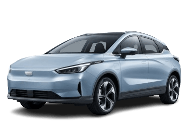
This article provides detailed fuse panel diagrams for the Geely Geometry C (1st generation, EV architecture, chassis code GE13) model years 2019–2023.
Fuse CF19 in the passenger compartment fuse panel powers the rear USB port.
Passenger Compartment Fuse Panel
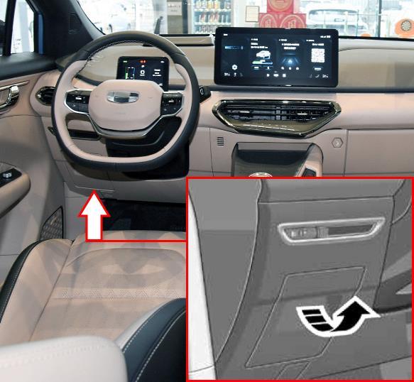
The fuse block is located on the driver’s (left) side of the dashboard. Remove the glove box to gain access.
| Diagram | ||
|---|---|---|
|
||
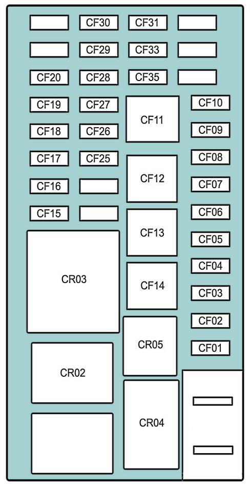
| No. | Rating (A) | Protected Circuit / Component |
| CF01 | 30 | Headlamps |
| CF02 | 30 | Headlamps |
| CF03 | 10 | Diagnostic Link Connector (DLC) |
| CF04 | 30 | Body Control Module (BCM) |
| CF05 | 30 | Power door locks |
| CF06 | 10 | Head-Up Display (HUD), 360-degree camera system, RF drive module, camera module, EV communication controller |
| CF07 | 10 | Power mirror switch, electronic shifter, wireless charger, auxiliary console switch bank |
| CF08 | 5 | Keyless entry system |
| CF09 | 10 | Infotainment display |
| CF10 | 15 | Electronic Steering Column Lock (ESCL) |
| CF11 | 25 | Unused |
| CF12 | 20 | Smart door handle control module |
| CF13 | 20 | Power sunroof |
| CF14 | 25 | Right power window |
| CF15 | 10 | Battery Management System (BMS), Central Control Unit (IG2) |
| CF16 | 15 | Rear window wiper |
| CF17 | 15 | Windshield washer pump |
| CF18 | 20 | Redundant power supply |
| CF19 | 10 | Central Control Unit, 360-degree surround-view system, rear USB port |
| CF20 | 10 | Dashcam (DVR), driver information system main unit, auto-dimming rearview mirror |
| CF25 | 10 | Sunroof, power sunshade, Electronic Toll Collection (ETC), seat memory module (IG1) |
| CF26 | 10 | Central Control Unit, keyless entry module, telematics control unit (IG1) |
| CF27 | 15 | Engine compartment fuse box (IG1) |
| CF28 | 10 | Steering angle sensor, Electric Power Steering (EPS), electronic shifter, Electronic Steering Column Lock (ESCL), auxiliary console switch bank |
| CF29 | 10 | Airbag Control Module (ACM) |
| CF30 | 10 | Electronic Parking Brake (EPB) module, climate control unit (HVAC) |
| CF31 | 5 | Interior lighting |
| CF33 | 10 | Climate control unit (HVAC), telematics control unit |
| CF35 | 15 | Infotainment system main unit |
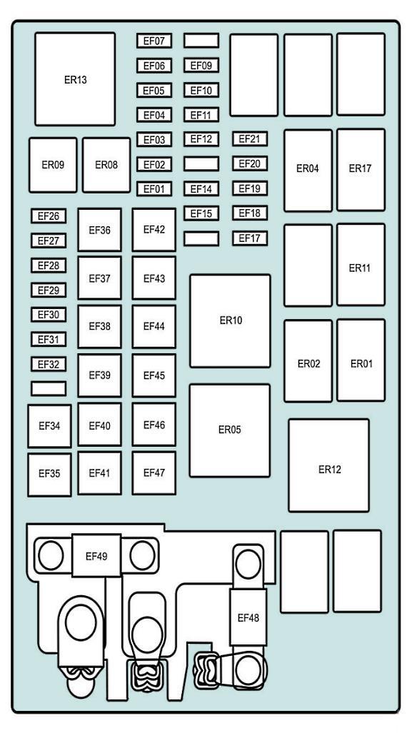
Engine Compartment Fuse Box
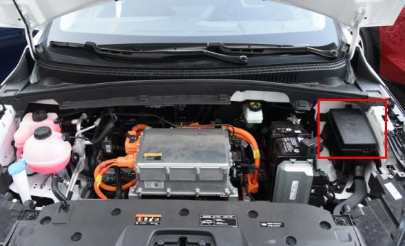
The fuse box is located under a protective cover in the engine compartment, adjacent to the battery.
| Diagram | ||
|---|---|---|
|
||
| No. | Rating (A) | Protected Circuit / Component |
| EF01 | 7.5 | Brake light switch |
| EF02 | 10 | Vehicle Control Unit (VCU) |
| EF03 | 15 | Integrated Power Controller (IPC) |
| EF04 | 15 | Battery / Charging Management System (BMS) |
| EF05 | 30 | Turn signals |
| EF06 | 10 | Front turn signals |
| EF07 | 15 | Horn |
| EF09 | 10 | Cooling fan relay |
| EF10 | 7.5 | Coolant pump relay |
| EF11 | 5 | High-speed cooling fan relay |
| EF12 | 5 | Low-speed cooling fan relay |
| EF14 | 10 | Coolant pump and cooling fan relay |
| EF15 | 20 | Vehicle Control Unit (VCU) |
| EF17 | 7.5 | Electronic Stability Control (ESC) module / Vehicle Control Unit (VCU) |
| EF18 | 7.5 | Integrated power / charging controller |
| EF19 | 10 | Intelligent brake booster / brake lights |
| EF20 | 7.5 | Acoustic Vehicle Alerting System (AVAS) / mmWave radar |
| EF21 | 10 | Heated side mirrors |
| EF26 | 15 | A/C compressor relay |
| EF27 | 7.5 | Active grille shutter |
| EF28 | 30 | Front windshield wipers |
| EF29 | 7.5 | A/C compressor controller |
| EF30 | 5 | State of charge (SoC) indicator |
| EF31 | 15 | Electric coolant pump |
| EF32 | 30 | Audio amplifier |
| EF34 | 25 | Heated rear window |
| EF35 | 30 | Cooling fan (low speed) |
| EF36 | 60 | Smart brake booster (iBooster) |
| EF37 | 25 | Front passenger power seat |
| EF38 | 40 | Vacuum / scavenge pump |
| EF39 | 25 | Passenger compartment fuse panel (IG2) |
| EF40 | 25 | Driver power seat |
| EF41 | 25 | Left power window |
| EF42 | 60 | Passenger compartment fuse panel (B+) |
| EF43 | 30 | Electronic Parking Brake (EPB) - left |
| EF44 | 30 | Electronic Parking Brake (EPB) - right |
| EF45 | 60 | Electronic Stability Control (ESC) module |
| EF46 | 40 | Stability control motor / hydraulic unit |
| EF47 | 50 | Passenger compartment fuse panel |
| EF48 | 80 | Electric Power Steering (EPS) |
| EF49 | 150 | On-Board Charger (OBC) |
