Table of Contents
In this article, we will take a detailed look at the fuse diagrams for the Geely Coolray car (first generation / SX11): 2018, 2019, 2020, 2021, 2022, 2023, 2024 of release.

Fuse IF19 in the passenger compartment is responsible for the cigarette lighter.
In the passenger compartment
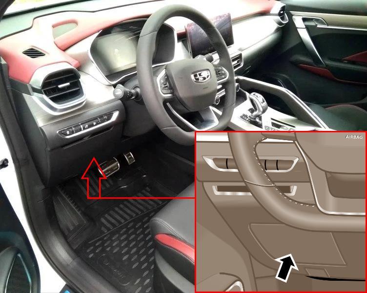
The distribution box is on the driver's side. To access it, you need to open the inspection hatch.
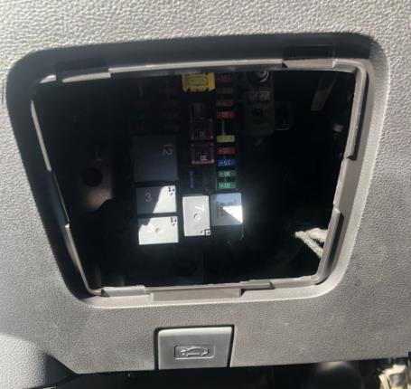
Access example.

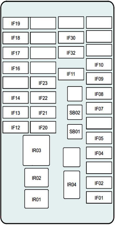
Example of the diagram from the interior block cover.
| Diagram | ||
|---|---|---|
|
||
| No. | Amps | Description |
| IF01 | 30 | BCM module / exterior lights |
| IF02 | 30 | interior lamps / BCM |
| IF04 | 10 | Rear view mirrors (BCM) / footwell lamps / HPS / anti-theft coils |
| IF05 | 20 | Central lock / BCM |
| IF07 | 10 | FCS/EDR |
| IF08 | 5 | Gateway |
| IF09 | 5 | Screen/IN |
| IF10 | 10 | General illumination lamps / TCM |
| IF11 | 20 | independent memory |
| IF12 | 10 | Fan relay |
| IF13 | 15 | Electric motor washer |
| IF14 | 10 | Seat heater |
| IF16 | 10 | Rear wiper |
| IF17 | 10 | BCM/MMI/MIRROR/USB/EDR ACC+fuse |
| IF18 | 20 | Front heater block |
| IF19 | 15 | Power outlet |
| IF20 | 10 | 360/Middle passage switch/EPB switch fuse |
| IF21 | 5 | Airbags |
| IF22 | 10 | BCM/IP/E-CALL/ Interior rearview mirror anti-dazzling/ TCM fuse |
| IF23 | 10 | UEC IG1 |
| IF30 | 10 | E-call module |
| IF32 | 15 | MMI module |
| SB01 | 30 | Seat adjustment drive |
| SB02 | 30 | Sunroof |
| IR01 | - | |
| IR02 | - | |
| IR03 | Auxiliary relay | |
| IR04 | Wiper relay | |
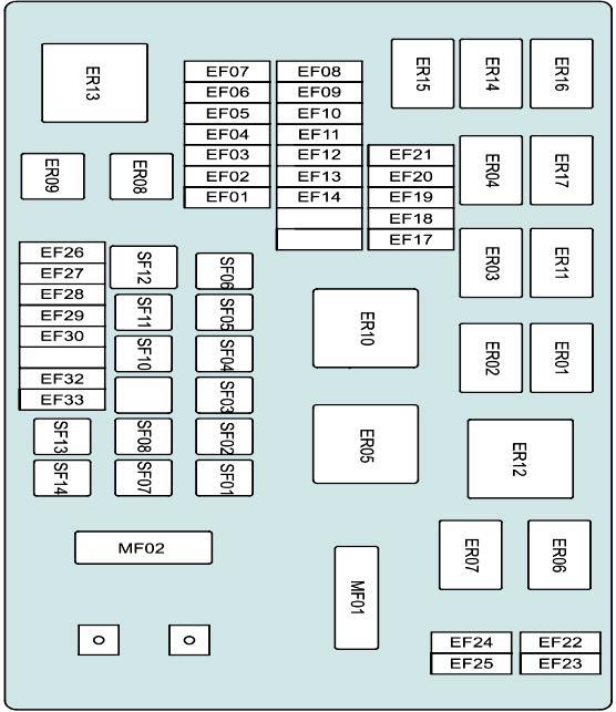
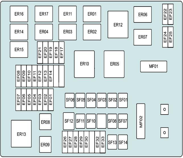
In the engine compartment

The fuse box is located on the left side of the engine compartment. To access, loosen the side fixed tab of the lock and remove the cover.

General view.
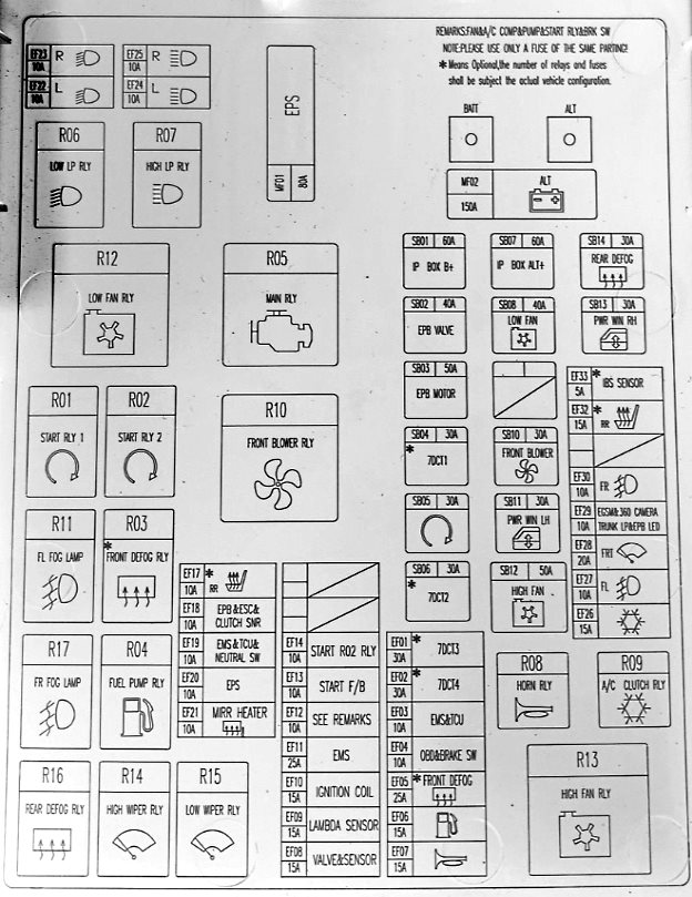
Example of the diagram from the block cover.
| Diagram | ||
|---|---|---|
|
||
| No. | Amps | Description |
| MF01 | 80 | Power steering |
| MF02 | 150 | Generator |
| SB01 | 60 | IP BOX B+ Fuse |
| SB02 | 40 | EPB system (electric parking brake) |
| SB03 | 50 | EPB motor |
| SB04 | 30 | 7DCT1 |
| SB05 | 30 | Starter |
| SB06 | 30 | 7DCT2 |
| SB07 | 60 | IP BOX ALT+ fuse |
| SB08 | 40 | Low speed fan |
| SB10 | 30 | Cabin fan |
| SB11 | 30 | Left power window |
| SB12 | 50 | High speed fan |
| SB13 | 30 | Right power window |
| SB14 | 30 | Rear window heating |
| EF01 | 30 | 7DCT3 |
| EF02 | 30 | 7DCT4 |
| EF03 | 10 | TCU/EMS control unit |
| EF04 | 10 | Stop/OBD switch |
| EF05 | 25 | Heated windshield |
| EF06 | 15 | Fuel pump fuse |
| EF07 | 15 | Horn |
| EF08 | 15 | Solenoid valve |
| EF09 | 15 | oxygen sensor |
| EF10 | 15 | Ignition coils |
| EF11 | 25 | EMS control unit |
| EF12 | 10 | Relay (Fan/Oil Pump/Compressor/Starter/Vacuum Pump)/ SOV |
| EF13 | 10 | Starter Feedback |
| EF14 | 10 | Starter relay R2 |
| EF17 | 10 | Rear/front seat heater |
| EF18 | 10 | EPB/ESC/clutch pedal sensor |
| EF19 | 10 | EMS/TCU/neutral position sensor |
| EF20 | 10 | EPS control unit |
| EF21 | 10 | Rear view mirror heating |
| EF22 | 10 | Low beam left headlight |
| EF23 | 10 | Right low beam headlight |
| EF24 | 10 | Left high beam headlight |
| EF25 | 10 | Right high beam headlight |
| EF26 | 15 | Air conditioning compressor |
| EF27 | 10 | Left fog lamp |
| EF28 | 20 | Front wiper |
| EF29 | 10 | EGSM/360 Panorama/EPB LED+ fuse |
| EF30 | 10 | Right fog lamp |
| EF32 | 15 | Rear seat heater |
| EF33 | 5 | IBS |
| Purpose of relay modules | ||
|
||
| ER1 | Start relay 1 | |
| ER2 | Start relay 2 | |
| ER3 | Front defroster | |
| ER4 | Fuel pump relay | |
| ER5 | Main relay | |
| ER6 | Low beam headlights | |
| ER7 | High beam headlights | |
| ER8 | Horn | |
| ER9 | Air conditioning compressor | |
| ER10 | Front fan | |
| ER11 | Fog lights | |
| ER12 | Low cooling fan speed | |
| ER13 | High speed cooling fan | |
| ER14 | High speed wiper motor | |
| ER15 | Low speed wiper motor | |
| ER16 | Rear window heating | |
View and print PDF:
