The second generation of the Honda Fit compact car launched in 2007. The new body received a slightly modified front end, more "convex" due to the front windshield struts, which makes the silhouette of the car look very fresh. In this material, we will analyze in detail the fuse circuits (GE, GP, GG) of the 2st generation 2007, 2008, 2010, 2011, 2012, 2013, 2014, 2015 release.
Here you will find the locations and photos of the fuse boxes. The fuses responsible for the “Cigarette lighter” and “Fuel Pump” are highlighted in bold.
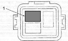
In the passeneger comparment

LHD models: Located on the driver's side under the steering column trim.
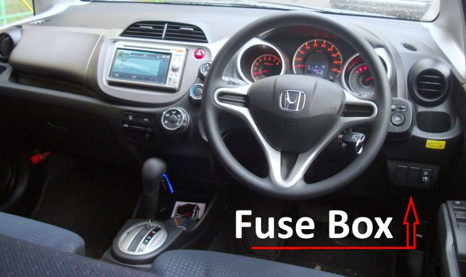
Located on the driver's side behind the cladding.
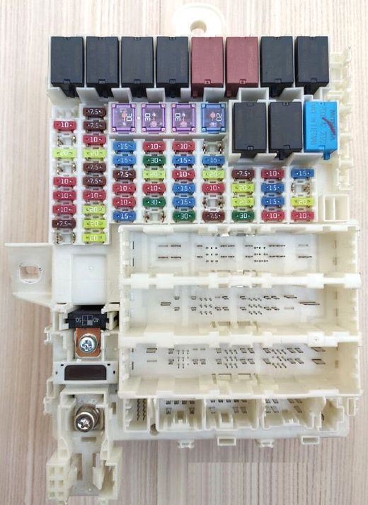
The photo shows an example.
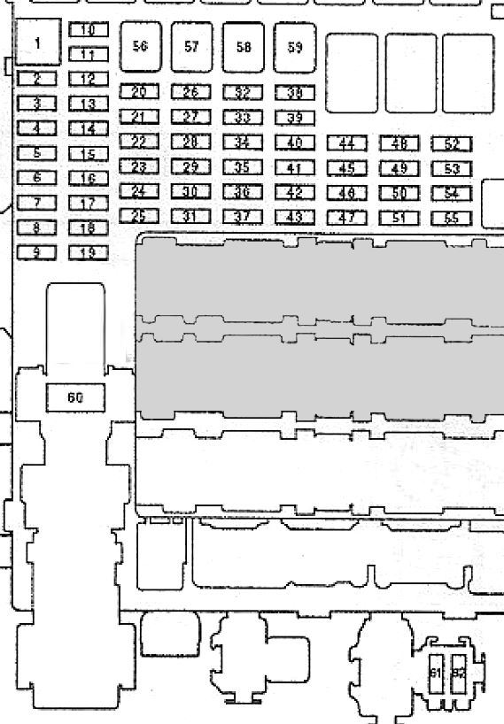
| Diagram | ||
|---|---|---|
|
||
| No. | Decoding | A |
| 1 | Reversing lights | 10 |
| 2 | Tire pressure monitoring system | 7.5 * |
| 3 | Power window regulator, driver's side | 20 |
| 4 | - | |
| 5 | Reversing lights | 10 |
| 6 | Passive Safety System (SRS) | 10 |
| 7 | Gearbox control unit | 10 |
| 8 | Passive Safety System (SRS) | 7.5 |
| 9 | Fog lights | 20* |
| 10 | Air conditioning | 7.5 |
| 11 | Anti-lock braking system AC (ABS) | 7.5 |
| 12 | Generator | 10 |
| 13 | Socket for connecting additional equipment, cigarette lighter fuse fit and jazz | 20 |
| 14 | Auxiliary equipment | 7.5 |
| 15 | Daytime lighting system | 7.5 * |
| 16 | Rear door glass wiper and washer | 10 |
| 17 | Power window regulator, front passenger side | 20 |
| 18 | Power window regulator, rear right door | 20 |
| 19 | Power window regulator, rear left door | 20 |
| 20 | Gasoline pump | 15 |
| 21 | Windshield washer | 15 |
| 22 | Instrument cluster | 7.5 |
| 23 | Alarm | 10 |
| 24 | Stop lights, horn | 15 |
| 25 | Windshield wiper drive | 15 * 1 |
| 26 | Heater | 10 |
| 27 | central locking | 30* |
| 28 | Headlights | 20 * 2 |
| 29 | parking lights | 10 |
| 30 | Cooling fan motor | 30 |
| 31 | - | |
| 32 | Right headlight (low beam) | 15 * 2 10 * 3 |
| 33 | Ignition | 15 |
| 34 | Left headlight (high beam) | 10 * 2 |
| Left headlight (low beam) | 10 * 3 | |
| 35 | Electric door lock | 15 |
| 36 | ||
| 37 | Anti-lock braking system ABS (ABS), stability control system (VSA) | 30 |
| 38 | Electric door lock | 15* |
| 39 | Engine management system | 15 |
| 40 | Heated front seats | 20* |
| 41 | No | - |
| 42 | No | - |
| 43 | A / C Compressor Electromagnetic Clutch | 7.5 |
| 44 | STS | 7.5 |
| 45 | Electric door lock | 20 * 1 |
| 46 | Electric roof blinds | 20 * 1 |
| 47 | Cooling fan motor | 30 |
| 48 | Left headlight (low beam), left headlight (high beam) | 15 * 2 10 * 3 |
| 49 | Electric door lock | 15* |
| 50 | 15* | |
| 51 | Right headlight (high beam) | 10 * 2 10 * 3 |
| 52 | DBW | 15 |
| 53 | No | - |
| 54 | Heated rear window | 20 * 1 |
| 55 | Heated side mirrors | 10 * 1 |
| 56 | Windshield wipers | 30 |
| 57 | Heater blower motor | 30 |
| 58 | Anti-lock braking system (ABS), stability control system (VSA) | 30 |
| 59 | Heated rear window | 30 * 4 20 * 5 |
| 60 | Ignition | 50/40 |
| 61 * | Audio system | 30 |
| 62 * | No | |
| Note : * - modification; * 1- models with anti-theft system; * 2 - models with halogen lamps, * 3 - models with xenon lamps, * 4 - models with side mirror heaters, * 5 - models without side mirror heaters. | ||
| Relay | ||

|
||
| 2 | Heater blower motor relay | |
| 7 | Relay (Drive By Wire) control system | |
| 5 | Ignition coil relay | |
| 3 | Mixture sensor relay | |
| 6 | Relay for engine control system No. 1 | |
| 10 | Engine management system relay # 2 (FUEL PUMP relay) | |
| 1 | Power window relay | |
| 4 | Lighting system relay 1 | |
| 20 | Lighting system relay 2 | |
| 8 | Heated rear window relay | |
| 9 | Starter relay | |
| Rest: wire harness | ||
In the engine comparment
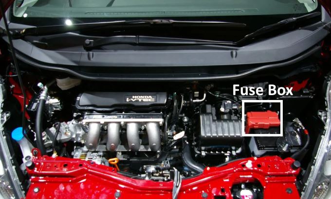
The distribution box is located on the positive terminal of the battery and consists of high-voltage fuse-links.
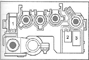
| Diagram of the power unit in the engine compartment Honda Fit / Jazz | ||
|---|---|---|
|
||
| No. | Description | A |
| 1 | Accumulator battery | 100 |
| 2 | Electric power steering | 60 (70) |
| 3 | Horn, brake lights, hazard warning lights | 20 |
| Note : () - left-hand drive models. | ||
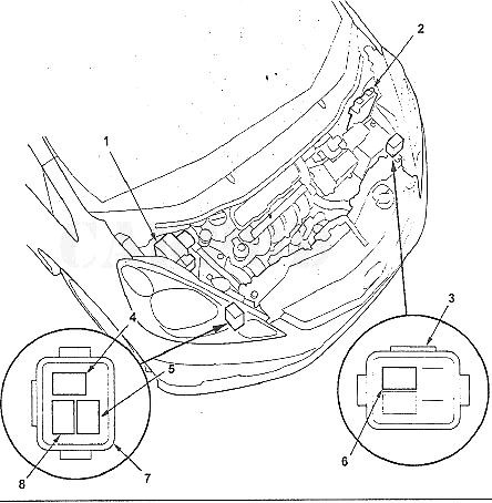
Location of relays and control units in the engine compartment . 1 - pressure modulator and VSA control unit or pressure modulator and ABS control unit 2 - electronic engine control unit, 3 - additional relay block No. 2, 4 - compressor electromagnetic clutch relay, 5 - cooling fan motor relay, 6 - brush defroster relay , 7 - additional relay block # 1, 8 - condenser fan motor relay.
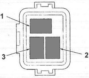
| Additional relay box #1 | |
|---|---|
|
|
| No. | Description |
| 1 | Air conditioning compressor electromagnetic clutch relay |
| 2 | Cooling fan motor relay |
| 3 | Condenser fan motor relay |
| Additional relay box #2 | |
|---|---|
|
|
| No. | Name |
| 1 | anti-icer brushes |
