The StepWGN minivan debuted on the market in 1996. It could accommodate 5-8 people, depending on the version, a side sliding door was used to access the passenger part of the cabin. In this article, we will take a detailed look at the fuse diagrams for the the 1st generation Honda StepWGN 1996, 1997, 1998, 1999, 2000, 2001, 2WD and 4WD with a B20V engine (2.0 l).

Here you will find the locations and photos of distribution boxes. The fuse responsible for the “Cigarette lighter” is highlighted in bold.
In the passenger compartment

Location of electronic control units (dashboard). 1 - navigation system electronic unit (models with navigation system), 2 - air conditioning electronic control unit / air conditioning and heater control panel, 3 - overspeed warning system unit, 8 - heater fan motor relay, 9 - distribution box under the instrument panel with driver's side, 10 - cigarette lighter relay, 11 - mirror folding system control unit, 12 - central locking control unit, 13 - sliding door electric drive relay.
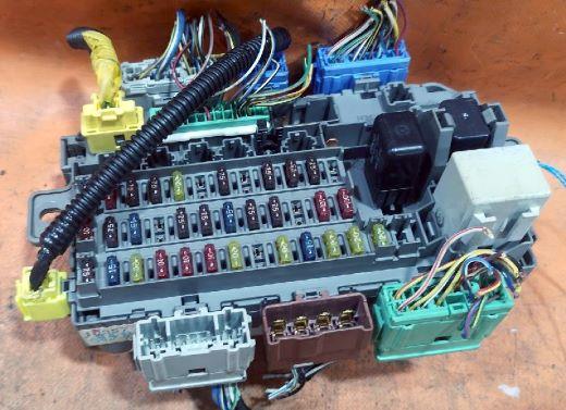
The photo is an example of a cabin fuse block.
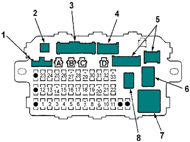
| Interior fuse box diagram (No. 9 in the picture) | ||
|---|---|---|
|
||
| No. | Decryption | Amps |
| 1 | Audio system unit, navigation system electronic unit | 15 |
| 2 | Central lock control unit | 20 |
| 3 | Rear window wiper motor, rear window washer pump | 10 |
| 4 | Right headlight (high beam) | 10 |
| 5 | Left headlight (high beam), high beam indicator | 10 |
| 6 | Rear sunroof motor | 20 |
| 7 | No | - |
| 8 | Front sunroof motor | 20 |
| 9 | No | - |
| 10 | Power window regulator, front passenger door | 20 |
| 11 | Power window driver's door | 20 |
| 12 | Relay-interrupter of direction indicators | 7.5 |
| 13 |
|
15 |
| 14 | No | - |
| 15 | Alternator, vehicle speed sensor, power supply voltage monitoring system unit, charging indicator |
7.5 |
| 16 | ABS ECM, Rear Defroster Relay | 7.5 |
| 17 | Rear A/C unit, A/C solenoid valve | 15 |
| 18 | Heater Fan Relay, Cooling Fan Motor Relay, A/C and Heater Control Panel | 7.5 |
| 19 | Reverse lamp relay | 7.5 |
| 20 | Empty | - |
| 21 | Right headlight (low beam) | 10 |
| 22 | Left headlight (low beam) | 10 |
| 23 | SRS electronic control unit (VB) | 10 |
| 24 | Rear sunroof relay, rear sunroof relay | 7.5 |
| 25 | Instrument Cluster, Shift Lock Solenoid Valve, Overspeed Warning Unit | 7.5 |
| 26 | Windshield wiper motor, windshield washer pump, integrated unit | 20 |
| 27 | No | - |
| 28 | cigarette lighter relay | 7.5 |
| 29 | No | - |
| 30 | Instrument panel illumination, integrated unit | 7.5 |
| 31 | Powertrain control module, injection main relay | 7.5 |
| 32 | Front position lights, rear position lights, license plate lamps | 7.5 |
| 33 | No | - |
| Relay | ||
| 1 | to the interior wiring harness | |
| 2 | to the main SRS connector | |
| 3 | to the instrument panel wiring harness, | |
| 4 | to the ignition switch | |
| 5 | to combo switch auxiliary socket | |
| 6 | power window relay | |
| 7 | turn signal relay | |
| 8 | rear window defroster relay | |
| AD | connector for connecting additional equipment. | |
In the engine compartment
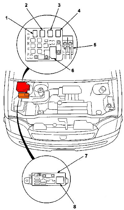
Location of distribution boxes in the engine compartment . 5 - main distribution box in the engine compartment, 7 - ABS fuse box,

General view of the main one.
| Main fuse box diagram (No. 6 in the picture) | ||
|---|---|---|
|
||
| No. | Decryption | Amps |
| 41 | Battery | 100 |
| 42 | Ignition switch (+B) | 40 |
| 43 | Interior lamp, diagnostic connector | 7.5 |
| 44 | Injection system main relay (fuel pump fuse) | 15 |
| 45 | Not used | - |
| 46 | Power windows | 40 |
| 47 | Audio system, navigation system electronics, powertrain control unit |
7.5 |
| 48 | Light control switch | 30 |
| 49 | No | - |
| 50 | Rear window heater | 20 |
| 51 | Sliding Door Motor Relay ( Sliding Door Models ) | 20 |
| 52 | Horn, brake lights | 15 |
| 53 | Relay-interrupter of direction indicators | 10 |
| 54 | Central locking control unit, sunroof motor | 40 |
| 55 | Heater fan motor | 40 |
| 56 |
|
20 |
| 57 | Cooling fan motor | 20 |
| Relay | ||
| 1 | to terminal "B" of the generator (engine wiring) | |
| 2 | to battery positive terminal (starter wiring) | |
| 3 | condenser fan motor | |
| 4 | A/C Compressor Solenoid Clutch Relay | |
| 5 | cooling fan motor relay | |
| 6 | heater fan motor | |
| ABS fuse box (#7 in the picture) | ||
|---|---|---|
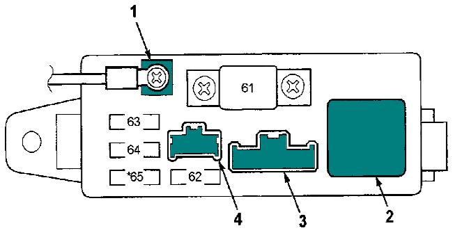
|
||
| No. | Protected circuit | Amps |
| 61 | ABS pump relay | 40 |
| 62 | ABS electronic control unit (MSK) | 10 |
| 63 | ABS solenoid valve (front) | 20 |
| 64 | ABS electronic control unit | 15 |
| 65 | No | - |
| 1 | to the battery positive terminal (starter wiring) | |
| 2 | ABS pump relay | |
| 3 | to engine compartment wiring harness | |
| 4 | to main wiring harness | |
