Table of Contents
In this article, we will take a detailed look at the fuse diagrams for the Honda StepWagon car (second generation / factory index RF3, RF4, RF5, RF6, RF7, RF8 ): 2001, 2002, 2003, 2004, 2005 of release.

Fuses numbered 15 and 18 in the passenger compartment are responsible for protecting the electrical circuit of the cigarette lighter.
In the engine compartment
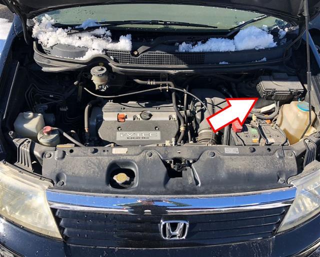
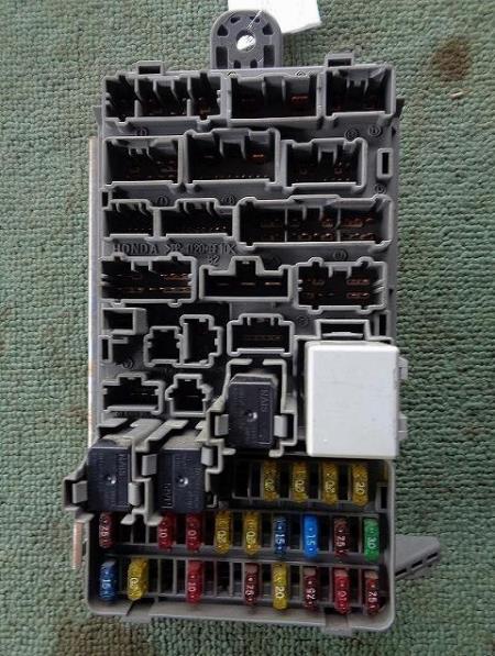
The fuse distribution box is located on the left side, near the windshield. To access it, you need to remove the protective cover.
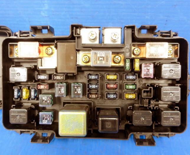
The photo shows an example.
| Diagram | ||
|---|---|---|
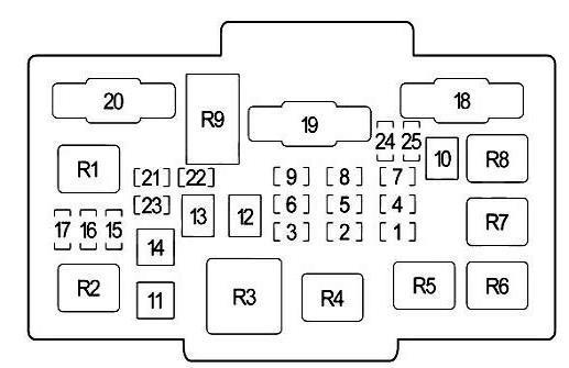
|
||
| No. | Description | Amps |
| R1 | Left headlight | - |
| R2 | Right headlight | - |
| R3 | fan motor | - |
| R4 | Rear window heating | - |
| R5 | A/C Compressor Clutch | - |
| R6 | radiator fan | - |
| R7 | Horn (beep) | - |
| R8 | Air conditioning condenser fan | - |
| R9 | Electrical Load Detector (ELD) Unit | - |
| 1 | A/C Compressor Clutch Relay, A/C Condenser Fan Relay | 20 |
| 2 | from 2005: Air-Fuel Ratio (A/F) Sensor Relay, Daytime Running Lights (DRL) Relay, PGM-FI Main Relay 1, Ignition Coil Relay, fuses #31, 32, 33, 34 in this box | 30 |
| before 2004: Tail light relay | 15 | |
| 3 | Interior Lights, Front Ceiling Light, Ignition/Key Light, Rear Ceiling Light, Rear Wiper Control Unit, XM Receiver A Connector, Spotlights | 15 |
| 4 | Radiator Fan Relay | 20 |
| 5 | Hazard Switch, Trailer Light Connector | 15 |
| 6 | from 2005: Rear light relay | 15 |
| before 2004: Main relay 1 PGM-FI | 10 | |
| 7 | Stop Lamp (Brake Pedal Position Switch), Horn Relay | 15 |
| 8 | from 2005: Throttle actuator control unit relay | 15 |
| 9 | Audio System, Reversing Lamp, Data Link Connector (DLC), Sensor Assembly, Immobilizer Control Unit, Keylees Receiver Unit, Multiplex Control Unit | 10 |
| 10 | Vehicle Stability Control (VSA) / ABS Modulator Control Unit | 30 |
| 11 | Rear defroster relay | 20 |
| 12 | Fan Motor Relay | 40 |
| 13 | Power Window Relay, Cabin Fuses No.: 7, 23 | 40 |
| 14 | fuses in cabin unit No.: 2, 3, 5, 15, 16 | 40 |
| 15 | Left headlight, daytime running light control module, sensor assembly | 20 |
| 16 | Power Door Interlock, Multiplexing Control Unit | 20 |
| 17 | Right headlight, daytime running light control module | 20 |
| 18 | Vehicle Stability Control (VSA) / ABS Modulator Control Unit | 30 |
| 19 | Battery, power distribution | 100 |
| 20 | Egnition lock | 50 |
| 21 | Not involved | - |
| 22 | Not involved | - |
| 23 | Not involved | - |
| 24 | Not involved | - |
| 25 | Not involved | - |
In the cabin
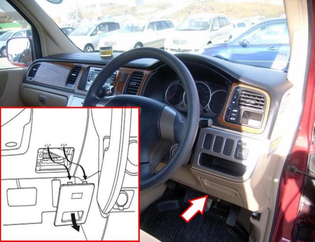
The fuse box is located behind the dashboard trim.
General view.
| Diagram | ||
|---|---|---|

|
||
| No. | Purpose | Amps |
| R1 | Starter (A/T) | - |
| R2 | Position Lamp Relay | - |
| R3 | Power windows | - |
| R4 | Hazard and direction indicators | - |
| 1 | Ignition coils | 15 |
| 2 | Rear Cigarette Lighter Socket Honda StepWagon | 10 |
| 3 | Daytime running lights, body electronics unit (Multiplex) | 10 |
| 4 | Alternator, Camshaft Position Sensor (CMP) A, Cruise Control, VSA OFF, Electrical Load Sensor (ELD), Intake Manifold Valve (IMT), Gasoline Vapor Emission System (EVAP), Secondary Oxygen Sensor (HO2S), Vehicle Stability Control (VSA), Speed Sensor (VSS) (M/T), Intake Manifold Length Variable Valve (IMRC), ABS Control Module (2003-2004) | 10 |
| 5 | Not involved | - |
| 6 | Air Fuel Ratio (A/F) Sensor Relay, Power Window Relay, Sunroof Relay, Power Window Control Module | 7.5 |
| 7 | sunroof relay | 20 |
| 8 | Instrument cluster, body electronics unit (Multiplex), transmission selector lock, audio system | 7.5 |
| 9 | Front passenger seat occupied detection system, front passenger weight sensor, rear wiper, wiper switch | 7.5 |
| 10 | Reverse lamp relay (A/T), reverse lamp switch (M/T), instrument cluster, key receiver, body electronics (Multiplex), anti-theft system, ABS control unit (2002), transmission selector lock relay (up to 2004) | 7.5 |
| 11 | Not involved | - |
| 12 | Daytime running lights (DRL), body electronics (Multiplex) | 7.5 |
| 13 | Airbag control unit (SRS) | 10 |
| 14 | A/C Compressor Clutch Relay, A/C Fan Relay, Heater Relay, Power Mirrors, Cooling Fan Relay, Heated Rear Window Relay, Air Recirculation Mode, Heated Seat Relay, Heater Control Module | 10 |
| 15 | from 2005: Front cigarette lighter socket relay | 15 |
| before 2004: Air-Fuel Ratio (A/F) Sensor Relay | 20 | |
| 16 | Seat heating relay | 20 |
| 17 | StepWagon 2 Fuel Pump Fuse , Engine Control Module (ECM/PCM), Front Passenger Airbag Deactivated Indicator, Immobilizer, Engine Control Module Main Relay (PGM-FI Main) 2, Airbag Control Module (SRS) | 15 |
| 18 | Audio system (since 2005), front and rear cigarette lighter socket | 15 |
| 19 | Hazard and direction indicators | 7.5 |
| 20 | Front wiper and washer, body electronics unit (Multiplex) | 20 |
| 21 | Not involved | - |
| 22 | Front passenger power window | 20 |
| 23 | Driver power window | 20 |
| 24 | Rear left power window | 20 |
| 25 | Rear right power window | 20 |
View and print PDF:

Im searching for my fuse box for honda stepwagon 2005 RF4.
The compenent i searching is 83 S7S-605 if used i want to know how much?am frm Brunei Darussalam Thank you. N can email me at margrate2083@gmail.com