In this article, we will take a detailed look at the fuse diagrams for the Honda StepWagon car (third generation / factory index RG1, RG2, RG3, RG4 ): 2005, 2006, 2007, 2008 and 2009 of release.

Fuse number 9 in the main cabin unit is responsible for protecting the electrical circuit of the cigarette lighter.
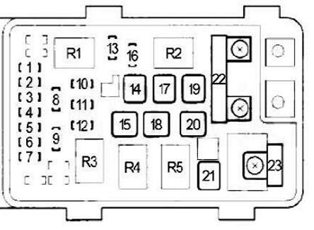
In the engine compartment
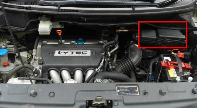
The fuse block is located near the battery. To access it, remove the protective cover.
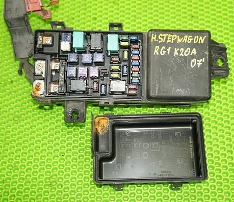
The photo shows an example.
| Diagram | ||
|---|---|---|
|
||
| No. | Description | Amps |
| R1 | Cooling fan | |
| R2 | air conditioner fan | |
| R3 | Rear window heating | |
| R4 | A/C Compressor Clutch | |
| R5 | Front heater | |
| 1 | Left headlight (low beam) | 10/15 |
| 2 | Rear differential star | 30 |
| 3 | Left headlight (high beam) | 10/15 |
| 4 | Clearance lamps, license plate lighting, instrument panel lighting, interior lighting, trailer connector, fuse: No. 7 | 15 |
| 5 | Right headlight (high beam) | 10 |
| 6 | Right headlight (low beam) | 10 |
| 7 | Reversing lamps | 7.5 |
| 8 | Diagnostic Connector (DLC), Engine and Transmission Control Module (PCM), Engine Control Module Relay (PGM-FI #1), Fuel Pump Relay (PGM-FI #2), Camshaft Position Sensor (CMP), Crankshaft Position Sensor ( CKP) A/B, injectors, fuse: No. 23 | 15 |
| 9 | air conditioner fan | 20 |
| 10 | Fog lights | 20 |
| 11 | Cooling Fan Control Relay, Cooling Fan | 20 |
| 12 | A/C Compressor Clutch | 7.5 |
| 13 | Stop lamps, horn, ignition switch, brake pedal position sensor | 15 |
| 14 | Heated rear window, rear body electronics unit (MICU) | 30 |
| 15 | Fuses of the main saloon unit: No. 5, 6, 7, 8, 9; fuse number 7 in the engine compartment | 40 |
| 16 | Hazard and turn signal relay, trailer connector (YOP) | 10 |
| 17 | Control unit and pressure modulator VSA / ABS | 30 |
| 18 | 30 / 40 | |
| 19 | Main cabin unit fuses: No. 1, 2, 3, 4 | 30 |
| 20 | Fuses of the main salon unit: No. 12, 14, 15, 16, 17 | 40 |
| 21 | heater | 40 |
| 22 | Alternator, fuses (engine bay fuse box) No. 1, 3, 4, 5, 6, 8, 9, 10, 11, 12, 14, 15, 19, 20, 21, 22 | 100 |
| Fuses (cabin fuse box #2): #1, 2, 3, 4, 5, 6, 8, 9 | 60 | |
| 23 | Egnition lock | 50 |
| Cars with anti-theft system: Power window relay, Main cabin fuses: No. 27, 28 | 50 | |
| Vehicles without an anti-theft system: Power window relay, Cabin main unit fuses: No. 27, 28 | 40 | |
In the cabin
There are two distribution boxes here, which are responsible for protecting the vehicle's electrical circuits.
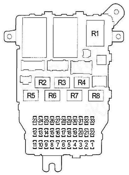
Main fuse box
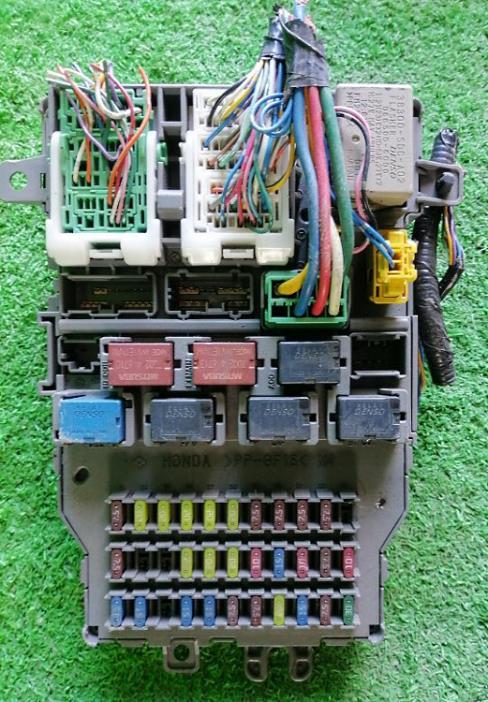
Located on the driver's side, at the bottom of the dashboard.
| Diagram | ||
|---|---|---|
|
||
| No. | Purpose | Amps |
| R1 | Hazard and turn signal lamps | |
| R2 | Ignition coils | |
| R3 | Engine control unit (PGM-FI No. 1) | |
| R4 | Cigarette lighter socket relay | |
| R5 | Honda stepwagon fuel pump relay (PGM-FI No. 2) | |
| R6 | Power windows | |
| R7 | Engine control unit (PGM-FI Subrelay) | |
| R8 | Starter | |
| 1 | Drive by wire system | 15 |
| 2 | Ignition Coils, Engine and Transmission Control Module (PCM), Engine Control Module (Main) Relay | 15 |
| 3 | Daytime Running Light Relay (DRL), Body Electronics Unit (MICU) | 10 |
| 4 | Laf heater | 15 |
| 5 | Audio system, navigation control unit, XM receiver, DVD player | 10 |
| 6 | Interior lighting, luggage compartment lighting, lamps in the doors | 7.5 |
| 7 | reversing lights | 10 |
| 8 | central locking | 20 |
| 9 | Cigarette lighter socket near the driver | 20 |
| 10 | Airbag Control Unit (SRS), Front Passenger Seat Occupancy Detection System (OPDS/ODS). front passenger airbag deactivated indicator | 7.5 |
| 11 | Front wiper | 7.5 |
| 12 | Tire pressure monitoring | 7.5 |
| 13 | Power passenger seat reclines | 20 |
| 14 | Power driver's seat | 20 |
| 15 | Lumbar support drive | 10 |
| 16 | Power seat | 20 |
| 17 | Power passenger seat slides | 20 |
| 18 | ACG | 15 |
| 19 | Fuel pump, immobilizer control unit (receiver) | 20 |
| 20 | IGN S.O.L. | 15 |
| 21 | Instrument Cluster, Shift Lock Module, Body Electronics Unit (MICU), Rear Body Electronics Unit, Auto Lighting System, Combination Switch, Parking Assist | 10 |
| 22 | Airbag control unit (SRS) | 10 |
| 23 | Engine Cooling Fan Diode, IGP (PGM-FI ECU) | 7.5 |
| 24 | Rear left power window | 20 |
| 25 | Rear right power window, ETS system | 20 |
| 26 | ETS module | 20 |
| 27 | Driver's window regulator, body electronics unit in the door | 20 |
| 28 | Sunroof and tailgate open/close relay | 20 |
| 29 | AFS module | 7.5 |
| 30 | A/CS module | 7.5 |
| 31 | SH-AWD module | 7.5 |
| 32 | ACC | 10 |
| 33 | Auxiliary | 7.5 |
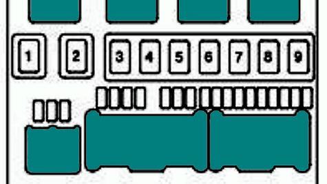
Auxiliary fuse block
Located on the passenger side.
| Diagram | ||
|---|---|---|
|
||
| No. | Description | Amps |
| 1 | SH-AWD module | 30 |
| 2 | Premium Audio Amplifier | 30 |
| 3 | Passenger power window | 30 |
| 4 | Driver's automatic belt tensioner | 30 |
| 5 | Power window right rear | 20 |
| 6 | Heated seats | 20 |
| 7 | Interior lighting | 7.5 |
| 8 | Passenger's automatic belt tensioner | 30 |
| 9 | Air conditioner | 7.5 |
View and print PDF:
