The i30 is a compact car from the Korean firm Hyundai Motor Company. Built on the same platform as the Kia cee'd, as well as it has five-door hatchback or station wagon bodies, petrol or diesel engines with a choice of manual or automatic transmission. In this article, we will take a detailed look at the fuse box diagrams for the Hyundai i30 (first generation; FD index) 2007, 2008, 2009, 2009, 2010, 2011 and 2012 years of manufacture.
Here you will find the locations and photos of distribution boxes. The fuses responsible for the “Cigarette lighter” and “Fuel Pump” are highlighted in bold.
In the engine compartment
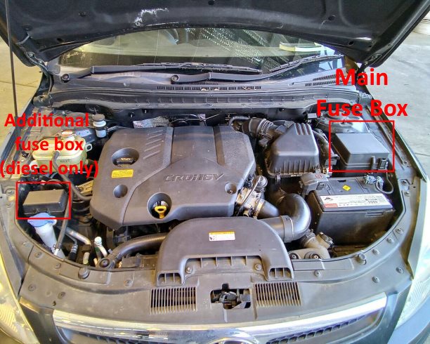
Location of underhood units.
Main fuse box
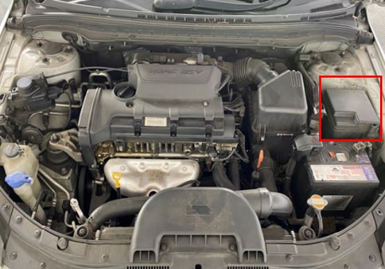
Located on the left side next to the battery and is covered with a protective cover.
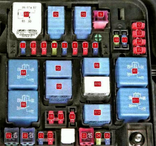
Type 1
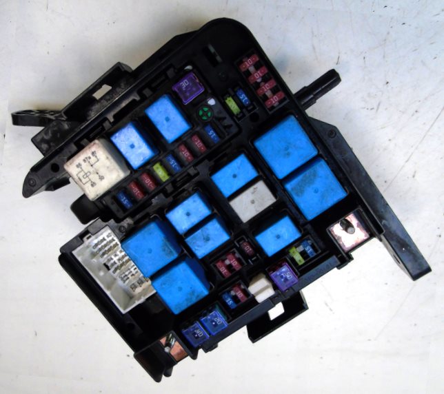
General view.
| Diagram | ||
|---|---|---|
|
||
| No. | Description | A |
| 1 | Engine control system sensors | 10 |
| 2 | Ignition system | 10 |
| 3 | Engine control system sensors | 10 |
| 4 | Electronic engine control unit | 20 |
| 5 | Fuel injectors, air conditioning system | 15 |
| 6 | Air conditioner | 10 |
| 7 | Electronic engine control unit | 10 |
| 8 | Hyundai i30 fuel pump fuse | 15 |
| 9 | Main relay | 30 |
| 10 | Reserve | 20 |
| 11 | Reserve | 15 |
| 12 | Stability Program (ESP), Anti-lock Braking System (ABS), Stability Sensor | 10 |
| 13 | Reverse light switch | 10 |
| 14 | Electronic engine control unit | 10 |
| 15 | Engine control system sensors | 10 |
| 16 | Reserve | 10 |
| 17 | Low beam right headlight | 10 |
| 18 | Low beam left headlight | 10 |
| 19 | Same | 40 |
| 20 | Stability Program (ESP), Anti-lock Braking System (ABS), Diagnostic Connector | 20 |
| 21 | Front fog lights | 15 |
| 22 | Reserve | 10 |
| 23 | Electronic control unit for interior electrical equipment | 50 |
| 24 | High beam | 20 |
| 25 | Sound signal (Horn) | 15 |
| R1 | Main relay | |
| R2 | Air conditioner relay | |
| R3 | Fuel pump relay | |
| R4 | Radiator fan relay | |
| R5 | High beam relay | |
| R6 | Horn relay | |
| R7 | Air conditioning blower relay (high speed) | |
| R8 | Starter relay | |
| R9 | Rear fog lamp relay | |
| R1 | Wiper relay | |
| R11 | A/C Fan Relay (Low Speed) | |
| R12 | Low beam relay | |
| The main fuse is located on the front wall of the unit. To get to it, unscrew two nuts and remove the wire lugs. | ||

|
||
| No. | Purpose | A |
| 1 | Electric power steering | 80 |
| 2 | Starter, ignition switch (lock) | 40 |
| 3 | Heated rear view mirrors | 40 |
| 4 | Electric fan of the ventilation (heating) and air conditioning system | 40 |
| 5 | Electric radiator fan for cooling system | 40 |
| 6 | Generator | 150 |
| 7 | Ignition switch (lock) | 30 |
| 8 | Electronic control unit for electrical equipment in the passenger compartment | 50 |
| 9 | Reserve | 50 |
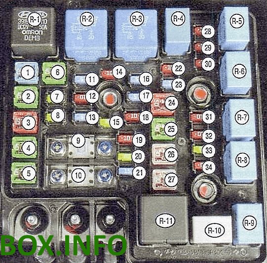
Type 2
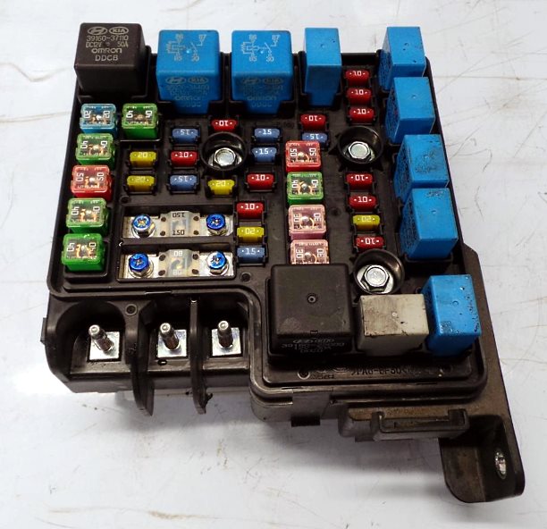
General view.
| Diagram | ||
|---|---|---|
|
||
| № | Description | A |
| 1 | ABS and ESP - ABS2 | 20 |
| 2 | ABS and ESP | 40 |
| 3 | Electronic control unit for electrical equipment of the passenger compartment - B + 1 | 50 |
| 4 | Heated mirrors - RR HTD | 40 |
| 5 | Electro fan - BLOWER | 40 |
| 6 | Electro Air Conditioning Fan - C / FAN | 40 |
| 7 | Headlight washer - H / LP WASHER | 20 |
| 8 | Reserve - SPARE | 20 |
| 9 | Generator - ALTERNATOR | 125 |
| 10 | Electro power steering - MDPS | 80 |
| 11 | Front fog lamps - FR FOG | 15 |
| 12 | Air Conditioning - A / CON | 10 |
| 13 | Emergency alarm system - HAZARD | 15 |
| 14 | Reserve | 10 |
| 15 | Reserve | 20 |
| 16 | Fuel pump fuse | 15 |
| 17 | Reserve - SPARE | 15 |
| 18 | Engine control unit - ECU1 | 10 |
| 19 | Engine control unit - ECU2 | 10 |
| 20 | Engine control unit - ECU3 | 20 |
| 21 | Fuel injectors, air conditioning - INJ | 15 |
| 22 | Sensors - SNSR2 | 10 |
| 23 | Sound signal - HORN | 15 |
| 24 | Electronic control unit for electrical equipment in the passenger compartment - B + 2 | 50 |
| 25 | Starter, ignition switch (lock) - ING2 | 40 |
| 26 | Ignition switch (lock) - IGN1 | 30 |
| 27 | Main relay - ECU | 30 |
| 28 | Stability control system ESP, anti-lock brake system ABS, exchange rate sensor - ABS | 10 |
| 29 | Ignition system - ECU2 | 10 |
| 30 | Reversing light switch - B / UP | 10 |
| 31 | Right headlight low beam - H / LP LO RH | 10 |
| 32 | Left headlight low beam - H / LP LO LH | 10 |
| 33 | High beam headlights - H / LP HI | 20 |
| 34 | Sensors - SNSR1 | 10 |
| R1 | Cooling fan relay (low speed) - C / FAN2 | |
| R2 | Cooling fan relay (high speed) - C / FAN1 | |
| R3 | Starter relay - START | |
| R4 | Fuel Pump Relay - F / PUMP | |
| R5 | Air conditioner relay - A / CON | |
| R6 | Headlamp Low Beam Relay - H / LP LO | |
| R7 | Horn relay - HORN | |
| R8 | Headlamp High Beam Relay - H / LP HI | |
| R9 | Rear fog lamp relay - FOG LP | |
| R10 | Wiper relay - WIPER | |
| R11 | Main relay - MAIN | |
Additional relay box
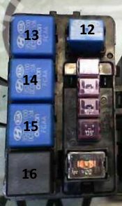
Used only in diesel engines.

Description
- 12 - fuel filter heater relay
- 13 - PTC heater relay #3
- 14 - PTC heater relay #2
- 15 - PTC heater relay #1
- 16 - glow plug relay
In the passenger compartment
There are two distribution boxes here that are responsible for protecting the electrical circuits.
Fuse box
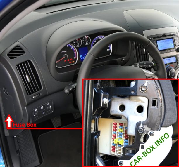
Located in the left end of the dashboard behind the protective cover.
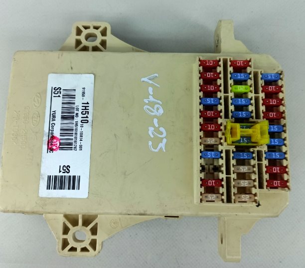
General view of the Hyundai i30 interior fuse box.
| Diagram | ||
|---|---|---|

|
||
| № | Description | Amps |
| 1 | Starter relay - START | 10 |
| 2 | Air conditioning control unit - A / CON SW | 10 |
| 3 | Heated exterior mirrors - HTD MIRR | 10 |
| 4 | Seat heating - SEAT HTR | 15 |
| 5 | Air Conditioning - A / CON | 10 |
| 6 | High beam lamps - HEAD LAMP | 10 |
| 7 | Windshield wiper - FR WIPER | 25 |
| 8 | Tailgate wiper - RR WIPER | 15 |
| 9 | Switching on the dipped beam during daytime - DRL OFF | 15 |
| 10 | Rear fog lamps - RR FOG | 10 |
| 11 | Power window control unit - P / WDW LH | 25 |
| 12 | Clock - CLOCK | 10 |
| 13 | Hyundai i30 Cigarette lighter fuse | 15 |
| 14 | Hatch, ignition control unit relay - DR LOCK | 20 |
| 15 | Heated windscreen relay - DEICER | 15 |
| 16 | Stop lights - STOP | 15 |
| 17 | Interior lighting - ROOM LP | 15 |
| 18 | Audio system, trip computer - AUDIO | 15 |
| 19 | Rear 5th door - T / LID | 15 |
| 20 | Power window lock (right side) - SAFETY P / WDW RH | 25 |
| 21 | Power window lock (left side) - SAFETY P / WDW LH | 25 |
| 22 | Power Windows - P / WDW | 25 |
| 23 | Power socket - P / OUTLET | 15 |
| 24 | Switch Block - T / SIG | 10 |
| 25 | Airbag Warning Lamp - A / BAG IND | 10 |
| 26 | Instrument panel - CLUSTER | 10 |
| 27 | Airbag - A / BAG | 15 |
| 28 | Door or ignition control unit - IGN1-A | 15 |
| 29 | Front Power Outlet - RR P / OUTLET | 15 |
| 30 | Rear right marker lamp - TAIL RH | 10 |
| 31 | Rear left marker lamp - TAIL RH | 10 |
Relay blocks
Under the panel there can be 2 additional relay blocks.
Location of relays in blocks
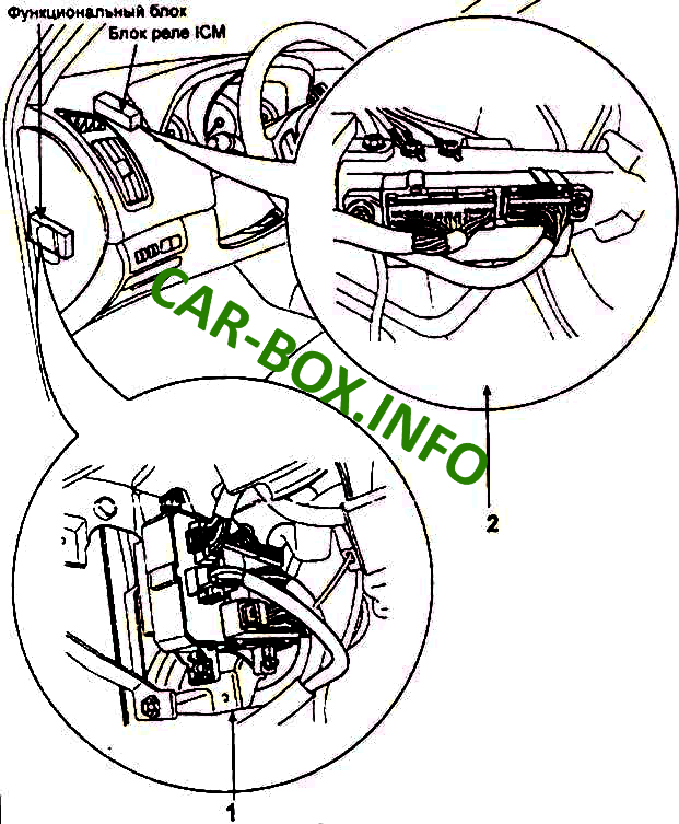
- rear light relay, power window relay, heater relay, tailgate relay
- Built-in-ICM relay box

Integrated circuit module (ICM) description:
- R1 – Door lock relay
- R2 – Door unlock relay
- R3 – Rear fog light
- R4 – Alarm horn relay
- R5 – Rain sensor relay, alarm horn relay
- R6 – Hazard warning light relay
- R7 – Deadlock relay
- R8 – Windscreen deicer
