Table of Contents
Most of the power supply circuits to the electrical equipment of the crossover are protected by fuses. Headlights, fan motors, fuel pump and other powerful current consumers are connected via relays. Protective elements are installed in distribution boxes, which are located in the passenger compartment and in the engine compartment.
Considered fuse diagrams Infiniti QX50 1st generation (J50) 2013, 2014, 2015, 2016 and 2017, 2018 model year.
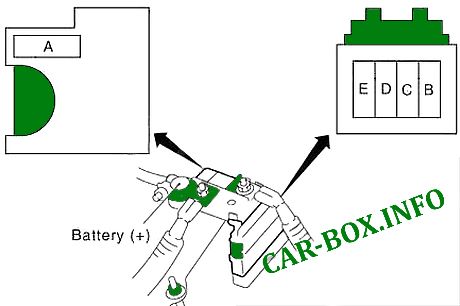
In the engine compartment
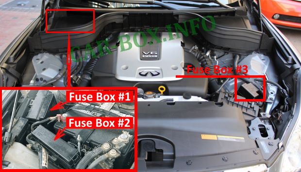
There are three blocks, as well as power elements on the battery.
| Fuse Box #1 | ||
|---|---|---|

The photo shows an example. |
||
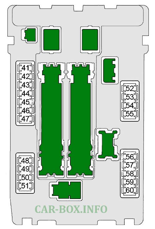
Diagram. |
||
| No. | Description | A |
| 41 | Fuel pump relay | 15 |
| 42 | Cooling fan relay | 10 |
| 43 | Snow Mode Switch, Transmission Control Module (TCM) | 10 |
| 44 | Injectors, Engine Control Module (ECM), BCM (Body Control Module) | 10 |
| 45 | ABS, Integrated Intelligent Cruise Control (ICC) Sensor, Steering Angle Sensor, Yaw Angle / Lateral Acceleration Sensor, Power Steering Control Unit, AWD Control Unit, Brake Power Control Unit, Blind Warning Control Unit zones (BSW), Side radar LH / RH | 10 |
| 46 | Air Fuel Ratio Sensors, Heated Oxygen Sensors | 15 |
| 47 | Combination switch | 10 |
| 48 | Not used | - |
| 49 | Air conditioner relay | 10 |
| 50 | Engine control module relay (intake timing control solenoid, condenser, ignition coils, engine control module, MAF sensor, EVAP canister purge volume control solenoid, exhaust timing control retarder magnet, EVAP canister ventilation control valve, variable valve event and lift control module (VVEL)) | 15 |
| 51 | Throttle control motor relay | 15 |
| 52 | Combination lamp Fron | 10 |
| 53 | Rear combination light, license plate light, VDC switch, adaptive front light system (AFS) switch, LDW switch, combination switch (coiled cable), clock, AV control unit, glove box light, control device, sonar cancel switch, all-round view Unit monitor control, power return switch (left and right), snow mode switch, seat heating switch (driver and passenger side), door mirror remote control switch, roof module (console lamp), warning switch, front power outlet, IBA Switch, Multifunction Switch | 10 |
| 54 | Far headlight, left | 10 |
| 55 | Headlight high right | 10 |
| 56 | Low beam headlamp, left | 15 |
| 57 | Headlight low right | 15 |
| 58 | Front fog lamp relay (2013-2015 - 10A; 2016-2017 - 15A) | 10 or 15 |
| 59 | 2016-2017: Relay for daytime running lights | 10 |
| 60 | Front wiper relay | 30 |
| Fuse Box #2 Diagram | ||
|---|---|---|

|
||
| No. | Description | A |
| 31 | Horn Relay, Generator | 15 |
| 32 | Rear Seat Back Power Return Regulator, Rear Seat Back Release Relay (Left), Rear Seat Back Release Relay (Right) | 30 |
| 33 | All-wheel drive control unit (AWD) | 10 |
| 34 | Audio, AV control unit, iPod adapter, Surround monitor control unit, Woofer, Camera control unit, Phone adapter unit, Satellite radio, Woofer | 15 |
| 35 | Seat heating relay | 15 |
| 36 | Transmission control module (TCM) | 10 |
| 37 | 2013-2017: horn relay 2 | 10 |
| 38 | Not used | - |
| F | Cooling fan relay | 50 |
| G | Ignition relay (fuses: "2", "3", "4"), IPDM E / R | 30 |
| H | Fuse: "61", "63" | 40 |
| I | Not used | - |
| J | - | |
| K | BCM (body control module), circuit breaker (auto drive control module, driver's seat control, lumbar support switch) | 40 |
| L | ABS | 30 |
| M | ABS | 50 |
| N | Variable valve and lift motor (VVEL) relay | 50 |
| O | Not used | - |
| R1 | Horn relay | |
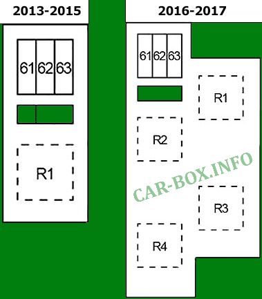
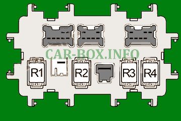
| Fuse Box #3 Diagram | ||
|---|---|---|
|
||
| No. | Decoding | A |
| 61 | Accelerator pedal drive | 10 |
| 62 | Not used | - |
| 63 | Brake booster control unit | 10 |
| Relay | ||
| R1 | 2013-2015: Cooling fan; | |
| 2016-2017: daytime running lights | ||
| R2 | Intelligent Cruise Control (ICC) Brake Hold | |
| R3 | Not used | |
| R4 | Sound signal number 2 | |
| Power battery box | ||
|---|---|---|
|
||
| No. | Appointment | A |
| A | Alternator, fuse: "B", "C" | 140 |
| B | Fuse: "F", "G", "K", "L", "M", "N", "31", "32", "33", "34", "35", "36", "37", "38" | 100 |
| C | Ignition relay (fuses: "41", "42", "43", "44", "45", "46", "47"), fuse: "48", "49", "50", "51 ". " | 80 |
| D | High beam relay (fuse: "54", "55"), low beam relay (fuse: "56", "57"), rear lamp relay (fuse: "52", "53"), fuse: " 58 "," 59 "," 60 " | 60 |
| E | Auxiliary relay (fuse: "18", "19", "20"), rear window heating relay (fuse: "13", "14", "15"), fan relay (fuse: "21", "22" ), Fuse: "6", "7", "9", "10", "11" | 80 |
In the passenger compartment
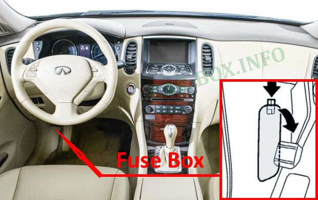
Located on the driver's side behind a plastic cover.
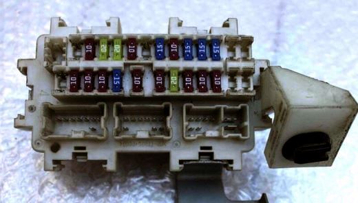
General view of the fuse box.
| Diagram | ||
|---|---|---|
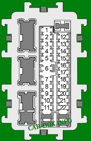
|
||
| No. | Description | A |
| 1 | Not used | - |
| 2 | Airbag diagnostic sensor unit, passenger classification control unit | 10 |
| 3 | Right and left aiming motor, shift lock relay, automatic cruise control (ASCD) brake switch, intelligent cruise control (ICC) brake switch, adaptive front lighting system (AFS) control unit, AFS switch, data link connector, LDW Switch, Sonar Control Unit, Lane Departure Warning Buzzer, Unified A / C Meter and Amplifier, Seat Heating Relay, AV Control Unit, Sonar Cancel Switch, Surround Monitor Control Unit, Buzzer, Phone Adapter Box, Compressor, Interior Mirror with auto dimming, lane camera unit, brake light switch, warning switch, ionizer, exhaust / odor detection sensor | 10 |
| 4 | Combined counter, back-up lamp relay | 10 |
| 5 | Not used | - |
| 6 | Key Socket, Intelligent Key Warning Buzzer, Data Link Socket, Unified Meter A / C Amplifier, Rear Seat Back Power Return Control, Rear Seat Back Unlock Relay (Left), Rear Seat Back Unlock Relay (Right), Clock, Interior Mirror with auto dimming, all around View Monitor Control Unit, Display Unit, Telephone Adapter Unit, Satellite Radio Tuner, Daytime Running Light Relay, Combination Counter | 10 |
| 7 | Brake Light Switch, BCM (Body Control Module), Intelligent Cruise Control (ICC) Brake Hold Relay | 10 |
| 8 | Amplifier BOSE | 20 |
| 9 | Key slot, push-button ignition switch | 10 |
| 10 | Seat Memory Switch, Auto Control Module, Driver's Seat Control, Door Mirror, BCM (Body Control Module) | 10 |
| 11 | Combined Meter, All Wheel Drive (AWD) Control Unit, Unified Meter A / C Amplifier | 10 |
| 12 | Not used | - |
| 13 | Heated rearview mirror | 10 |
| 14 | Heated rear window | 20 |
| 15 | 20 | |
| 16 | Not used | - |
| 17 | - | |
| 18 | Front power outlet, cigarette lighter fuse | 15 |
| 19 | Combination counter, unified counter and air conditioning amplifier, display, multifunction switch, AV control unit, adapter for iPod, BCM (body control module), sonar control unit, phone adapter unit, camera control unit, door mirror remote control switch, satellite radio Tuner , the control unit for the monitor of the circular view | 10 |
| 20 | Console power connector, QX50 cigarette lighter | 20 |
| 21 | Fan motor | 15 |
| 22 | 15 | |
| Back Side Relays | ||
|
||
| R1 | Ignition relay | |
| R2 | Heated rear window relay | |
| R3 | Auxiliary relay | |
| R4 | Front fan relay | |
View and print PDF:

Where is starter relay on this car. I have a qx50 that wouldn't start, and code shows starter relay malfunction.