Table of Contents
The power supply circuits for the electrical system of a premium Japanese vehicle are protected by fuses and relays. The elements are installed in distribution boxes located in the engine compartment and in the passenger compartment.

Infiniti QX56 / QX80 fuse diagrams for 2010, 2011, 2012, 2013, 2014, 2015, 2016, 2017 model years are reviewed.
In the engine compartment
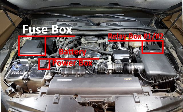
In the engine compartment there are two main distribution boxes with fuses and three additional boards with relay modules.
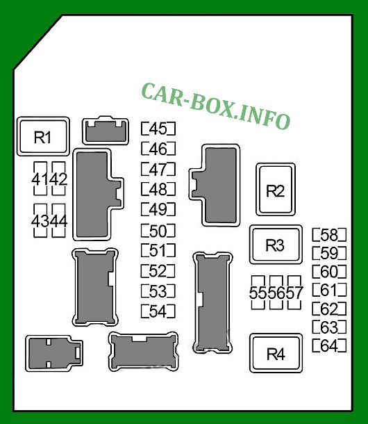
Fuse box #1
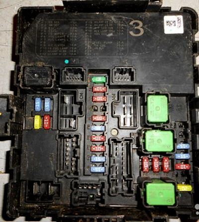
General view.
| Diagram | ||
|---|---|---|
|
||
| No. | Description | A |
| 41 | Heated rear window relay | 15 |
| 42 | 15 | |
| 43 | Engine control unit (ECM), immobilizer antenna amplifier, ECM relay (MAF sensor, variable valve timing (VVEL), air-to-fuel ratio sensor, oxygen sensor, fuel check valve, EVAP vent valve, injector relay ('14 - ' 17)) | 20 |
| 44 | Steering lock relay | 10 |
| 45 | Wiper relay | 30 |
| 46 | Tail light, trailer side light relay, license plate light | 10 |
| 47 | Interior lighting, glove box lighting, instrument panel lights, switch lights | 10 |
| 48 | - | - |
| 49 | Air conditioner relay | 10 |
| 50 | Front fog light | 15 |
| 51 | Right headlight (high beam) | 10 |
| 52 | Left headlight (high beam) | 10 |
| 53 | Left headlight (low beam) | 15 |
| 54 | Right headlight (low beam) | 15 |
| 55 | Reversing Lamp Relay, Trailer Power Relay, Transmission Control Module (TCM) | 10 |
| 56 | Transfer case control unit | 10 |
| 57 | ABS, brake light relay, yaw rate sensor | 10 |
| 58 | - | - |
| 59 | - | - |
| 60 | '10 -'13: Injector relay | 15 |
| 61 | Ignition coils, capacitor | 15 |
| 62 | Engine control unit (ECM) | 10 |
| 63 | - | - |
| 64 | Throttle valve relay | 20 |
| Relay | ||
| R1 | Heated rear window | |
| R2 | Ignition # 3 | |
| R3 | Ignition # 2 | |
| R4 | Ignition | |
Fuse box #2
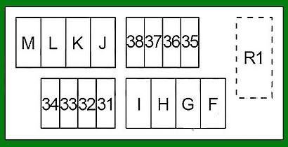
Diagram.
| No. | Description | A |
| 31 | Horn relay | 15 |
| 32 | Generator | 10 |
| 33 | Gas pedal | 10 |
| 34 | Transfer case unit | 10 |
| 35 | AV module, front display, video distributor, headrest monitors, telematics control unit (TCU ('14 -'17)) | 15 |
| 36 | Anti-theft alarm relay | 10 |
| 37 | IPDM (ignition relay # 2 (air suspension control unit), ignition relay # 3 (buzzer (warning systems), intelligent cruise control (ICC), accelerator pedal, driver assistance system (ADAS), side radars, lane keep track)) | 10 |
| 38 | Transmission control module (TCM) | 10 |
| F | Electric brake system, fuses "T", "V", "79", "84", "85", "86" | 40 |
| G | Ignition relay No. 1 (fuses "1", "2", "3", "4", "16"), fuses "12", "81", "82", "83", "U" | 40 |
| H | IPDM | 40 |
| I | Air Suspension Compressor Relay | 30 |
| J | Transfer case control unit | 30 |
| K | Body Electronics Module (BCM), Circuit Breaker (Driver Seat Adaptation System, Driver's Seat Control Module) | 50 |
| L | ABS | 30 |
| M | ABS | 50 |
| Relay | ||
| R1 | Sound signal | |
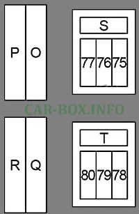
| Additional panel | ||
|---|---|---|
|
||
| No. | Decoding | A |
| P | Ignition relay (fuses "71", "72", "73", "74") | 50 |
| O | Variable valve timing system (VVEL) | 50 |
| R | Fuses "T", "79" | 50 |
| Q | '10 -'13: Fuses "S", "75", "76", "77" | 50 |
| '14 -'17: Fuses "S", "75", "76", "77", "87", "88", "89", "90" | 50 | |
| 75 | Heated wiper zone relay | 15 |
| 76 | Steering wheel heater relay | 10 |
| 77 | Pre-crash seat belt pretensioner system | 30 |
| S | Electric second row of seats | 30 |
| 78 | - | - |
| 79 | Inverter | 30 |
| 80 | Heated wiper zone relay, rear-view mirrors | 10 |
| T | Rear door control unit | 30 |
Relay box #1

Diagram.
| No. | Appointment | A |
| 71 | Engine control unit (ECM) | 30 |
| 72 | Cooling fan control unit | 10 |
| 73 | Fuel pump control unit | 15 |
| 74 | ABS | 10 |
| 87 | '14 -'17: Injector relay | 15 |
| 88 | '14 -'17: Daytime running light relay | 10 |
| 89 | 10 | |
| 90 | 10 | |
| Relay | ||
| R1 | Remote engine start | |
| R2 | - | |
| R3 | '10 -'13: Anti -theft alarm horn | |
| '14 -'17: Daytime running lights | ||
| R4 | - | |
| R5 | - | |
| R6 | Reversing lamps | |
| R7 | Heated steering wheel | |
| R8 | Intelligent Cruise Control (ICC) | |
| R9 | Heated wiper zone | |
| R10 | Rear air conditioner | |
| R11 | Brake light | |
| R12 | Air suspension compressor | |
| R13 | Ignition | |
| R14 | Variable valve timing system (VVEL) | |
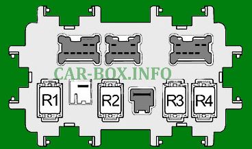
Relay box #2
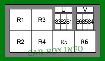
Diagram.
| No. | Decoding | A |
| 81 | Seat climate control relay | 15 |
| 82 | 15 | |
| 83 | Pre-crash seat belt pretensioner system | 30 |
| 84 | Direction indicators (trailer) | 15 |
| 85 | Reversing lamp relay | 10 |
| 86 | Side light relay (trailer) | 10 |
| U | Headlight washer relay | 30 |
| V | Trailer power relay | 30 |
| Relay | ||
| R1 | Seat climate control | |
| R2 | Right direction indicator (trailer) | |
| R3 | Headlight washers | |
| R4 | Left turn signal (trailer) | |
| R5 | Parking light (trailer) | |
| R6 | Food (trailer) | |
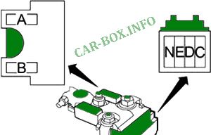
Power fuse panel
Located on the battery.
| Diagram | ||
|---|---|---|
|
||
| No. | Appointment | A |
| A | Alternator fuses "C", "D", "E" | 140 |
| B | Fuses "O", "P", "Q", "R" | 80 |
| C | Ignition relay (wiper relay (high speed), fuses "55", "56", "57", "60", "61", "62"), fuses "41", "42", "43", " 44 "," 64 " | 100 |
| D | Auxiliary relay (fuses "18", "19", "20"), ignition relay No.2 (fuses "13", "14", "15"), heater relay (fuses "21", "22"), fuses "5", "6", "7", "8", "9", "10", "11" | 80 |
| E | Fuses "31", "32", "33", "34", "35", "36", "37", "38", "F", "G", "H", "I", " J "," K "," L "," M " | 80 |
| N | High beam relay (fuses "51", "52"), low beam relay (fuses "53", "54"), side light relay (fuses "46", "47"), front fog light relay (fuses "50"), fuses "45", "49" | 60 |
In the passenger compartment
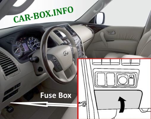
There is one distribution box in the cabin, on the back of which some relay modules are mounted.
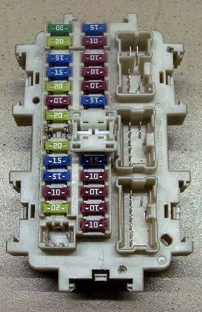
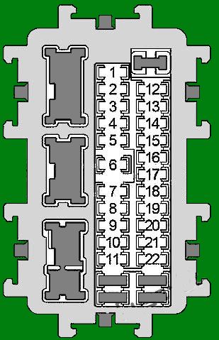
General view.
| Assigment of fuses in the passenger compartment | ||
|---|---|---|
|
||
| No. | Description | A |
| 1 | Combination switch | 10 |
| 2 | Airbags | 10 |
| 3 | Intelligent cruise control (ICC), cruise control (ASCD), brake light switch, headlight range control, diagnostic socket, steering angle sensor, instrument cluster, steering wheel heating, tire pressure monitoring system, power steering control unit control system, CAN bus, parking distance control system, adaptive front lighting (AFS), 120V socket, seat climate control relay | 10 |
| 4 | Rear air conditioning and heater, all-round vision system, air conditioning amplifier, ionizer, AV module, air pollution sensor, rear door control unit, electrochromic rearview mirror, parktronic control unit ('14 -'17), telematics control unit (TCU ('14 -'17)) | 10 |
| 5 | Amplifier BOSE | 15 |
| 6 | Diagnostic connector, clock, power second row of seats, smart key buzzer, pre-crash belt pretensioner system, light sensor, electrochromic rearview mirror, instrument cluster ('14 -'17) | 10 |
| 7 | Brake Light Switch, Body Electronics Module (BCM), Intelligent Cruise Control (ICC), Electric Brake System | 10 |
| 8 | Amplifier BOSE | 15 |
| 9 | Surround System, A / C Amplifier, Tailgate Control Module, Third Row of Seats, Tailgate Buzzer | 10 |
| 10 | Start button, seat memory, body electronics module (BCM) | 10 |
| 11 | Instrument cluster ('10 -'13) CAN bus | 10 |
| 12 | Auxiliary relay # 2 | 20 |
| 13 | Four-wheel drive, modes: "Snow", "Tow", "VDC off" | 10 |
| 14 | Heated second row seats | 15 |
| 15 | Heated front seats | 15 |
| 16 | Rear heater relay | 20 |
| 17 | - | - |
| 18 | '10 -'13: Center console socket | 20 |
| 19 | Power Mirrors ('10 -'13), Parktronic Control Unit ('10 -'13), Surround View System, A / C Amplifier, Multifunction Switch, AV Module, Front Display, Video Distributor, Power Windows ('14 -'17), Amplifier BOSE ('14 -'17) Telematics control unit (TCU ('14 -'17)) | 10 |
| 20 | Front socket, luggage compartment socket, No.2 auxiliary relay | 20 |
| 21 | Front heater | 15 |
| 22 | 15 | |
| Relay | ||
|
||
| R1 | Ignition 1 | |
| R2 | Ignition 2 | |
| R3 | Subsidiary | |
| R4 | Heater | |
View and print PDF:

Hello, any idea where I can find the fuse box #2 on a 2012 QX56?
I’ve looked EVERYWHERE for the suspension air compressor relay “I” but can’t find it.
Thanks in advance.