
In autumn 2005, the fifth-generation Mercedes-Benz S-Class was unveiled at the Frankfurt International Motor Show under the chassis code W221. The new S-Class was slightly wider, longer, and taller than its W220 predecessor, and introduced three powerful new engines with up to a 26% increase in power output. This article provides detailed fuse box diagrams and relay assignments for the Mercedes-Benz W221 / C216 (5th Gen S-Class / CL-Class: S350, S450, S500, S63 AMG, S65 AMG) covering model years 2005 through 2009.

Below you will find the locations, photos, and assignments for the fuse and relay distribution boxes. Fuses for the “Cigarette Lighter” and “Fuel Pump” are highlighted in bold.
Luggage Compartment Fuse Box
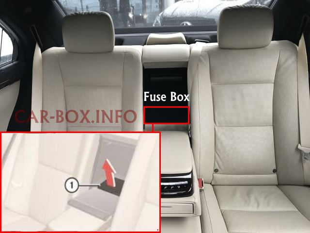
Access is from inside the passenger compartment. Fold down the center armrest, then remove the trim panel and plastic cover.
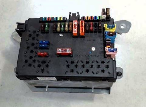
Luggage compartment fuse box unit layout.
| Diagram | ||
|---|---|---|

|
||
| No. | Relay Assignment | |
| M | Terminal 15 relay | |
| N | Terminal 15R relay | |
| O | Power outlet relay | |
| P | Heated rear window relay | |
| Q | Intercooler coolant circulation pump relay | |
| R | Cigarette lighter relay (Mercedes-Benz W221 / C216) | |
| S | Fuel pump relay | |
| No. | Circuit / Component Protected | A |
| 115 | Heated rear window | 50 |
| 116 | Engine M275: Intercooler coolant circulation pump | 10 |
| 117 | Rear cigarette lighter fuse | 15 |
| 118 | Engines M272, M273, OM642: Mercedes-Benz W221 / C216 fuel pump fuse | 30 |
| 119 | Front center console control panel | 7.5 |
| 120 | Not used | - |
| 121 | Audio tuner control module | 10 |
| 122 | COMAND control module | 7.5 |
| 123 | Front right reversible seatbelt tensioner | 40 |
| 124 | Front left reversible seatbelt tensioner | 40 |
| 125 | Not used | - |
| 126 | Overhead control panel module | 25 |
| 127 | Multicontour seat pneumatic pump | 30 |
| Dynamic seat control pneumatic pump | ||
| 128 | Engine M275: Fuel pump control module | 25 |
| 129 | Overhead control panel module | 25 |
| 130 | C216: Electric parking brake control module | 30 |
| 131 | Rear window antenna amplifier module | 7.5 |
| 133 | Trailer recognition control module | 15 |
| 134 | Trunk 12 V power outlet | 15 |
| 135 | Radar sensor control module (SGR) | 7.5 |
| Front short-range radar sensor module | ||
| Rear short-range radar sensor module | ||
| 136 | Not used | - |
| 137 | - | |
| 138 | - | |
| 139 | Rear seat backrest refrigerator box | 15 |
| 140 | 12 V power outlet | 15 |
| 141 | Rearview camera control module | 5 |
| 142 | Parktronic (PTS) control module | 7.5 |
| DISTRONIC PLUS radar sensor control module (SGR) | ||
| 143 | Rear seat control module | 25 |
| 144 | 25 | |
| 145 | Trailer recognition control module | 20 |
| 146 | 25 | |
| 147 | Trunk lid control module (HDS) | 30 |
| 148 | Universal Handy Interface (UHI) control module | 7.5 |
| 149 | Voice control system (VCS / SBS) control module | 5 |
| 150 | TV combo tuner (Analog/Digital) | 7.5 |
| 151 | Electric parking brake control module | 25 |
| 152 | Rear window antenna amplifier module | 7.5 |
In the Passenger Compartment
There are two fuse boxes located in the passenger compartment to protect the vehicle’s electrical circuits.
Main Fuse Box (Driver Side)
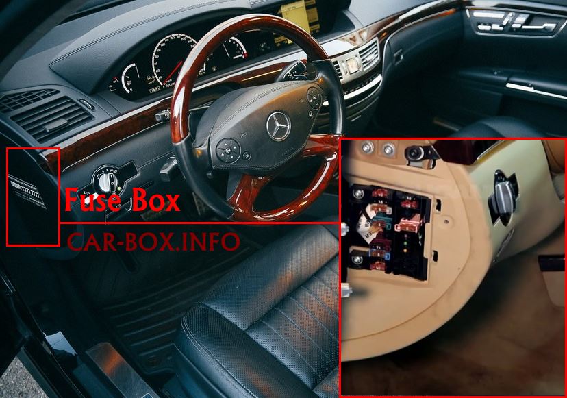
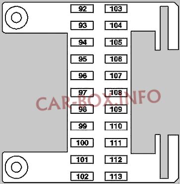
Located on the driver’s side, behind the end panel of the instrument panel/dashboard.
| Diagram | ||
|---|---|---|
|
||
| No. | A | Circuit / Component Protected |
| 92 | 40 | Front left seat control module |
| 93 | 7.5 | Supplemental Restraint System (SRS) control module |
| Weight Sensing System (WSS) control module (USA) | ||
| 94 | - | Not used |
| 95 | - | Not used |
| 96 | 5 | Tire pressure monitoring system (RDK) control module (Siemens) |
| 97 | 7.5 | W221: Rear seat audio/video entertainment control module |
| 98 | - | Not used |
| 99 | - | Not used |
| 100 | - | Not used |
| 101 | 10 | Rear left seat display screen |
| Rear right seat display screen | ||
| 102 | 40 | Front right seat control module |
| 103 | 7.5 | Electronic Stability Program (ESP) control module |
| 104 | 40 | Audio tuner control module |
| 105 | - | Not used |
| 106 | 10 | Electronic Toll Collection (ETC) control module (Japan) |
| 107 | 5 | C216: Satellite Digital Audio Radio (SDAR) module |
| 108 | 5 | Rear automatic climate control panel |
| 109 | 15 | W221: Intermediate connector for rear cabin blower fan |
| 110 | 7.5 | W221: Rear left and right seat backrest control module |
| 111 | 5 | Rear seat heating (HBF) control module |
| 112 | 5 | W221: Front left and right door control modules |
| 113 | - | Not used |
Auxiliary Fuse Box (Passenger Side)
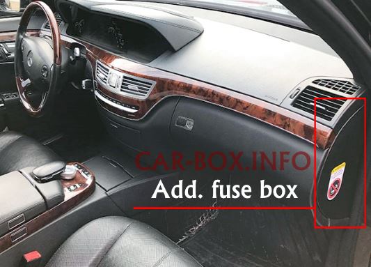
Located on the passenger side, behind the end panel of the instrument panel/dashboard.
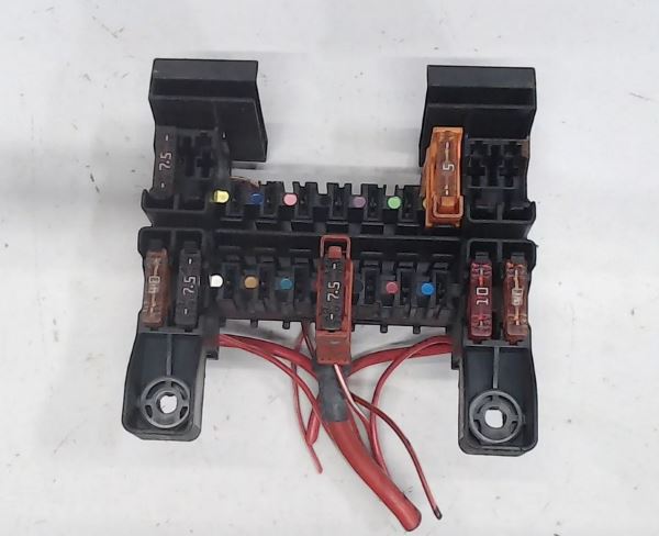
Photo showing an example layout of the dashboard side fuse box.
| Diagram | ||
|---|---|---|

|
||
| No. | A | Circuit / Component Protected |
| 70 | 40 | C216: Left door control module |
| W221: Front right door control module | ||
| 71 | 15 | KEYLESS-GO control module |
| 72 | - | Not used |
| 73 | 5 | COMAND control module (Japan) |
| 74 | 30 | Trunk lid control module (HDS) |
| 75-78 | - | Not used |
| 79 | 7.5 | Alarm siren with backup battery |
| 80 | 40 | C216: Left door control module |
| W221: Front left door control module | ||
| 81 | 30 | Rear control module |
| 40 | Rear left door control module | |
| 82 | 30 | Rear control module |
| 40 | Rear right door control module | |
| 83 | 30 | DIRECT SELECT automatic transmission servo module (A80) |
| 84-89 | - | Not used |
| 90 | 20 | C216: Auxiliary heater (STH) |
| W221: Auxiliary heater (STH) or heater booster (ZUH) | ||
| 91 | 5 | Radio remote control receiver for auxiliary heater (STH) |
In the Engine Compartment
There are two distribution boxes in the engine compartment that protect the vehicle’s electrical circuits.
Main Fuse Box
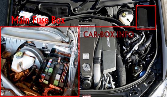
The main engine compartment fuse box is located at the rear right side of the engine bay.
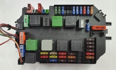
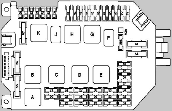
General view of the main fuse box.
| Diagram | ||
|---|---|---|
|
||
| No. | Relay Assignment | |
| A | Secondary air injection pump relay | |
| B | AIRMATIC suspension compressor relay | |
| C | Engine circuit terminal 87 relay | |
| D | Circuit terminal 15 relay | |
| E | Chassis circuit terminal 87 relay | |
| F | Dual-tone horn relay | |
| G | Circuit terminal 15R relay | |
| H | Starter circuit terminal 50 relay | |
| J | Starter circuit terminal 15 relay | |
| K | Heated windshield washer / wiper park heater relay | |
| No. | A | Circuit / Component Protected |
| 20 | 10 | Engine OM642: CDI control module |
| Engines M272, M273, M275: ME-SFI control module | ||
| 21 | 20 | Engines M272, M273, M275: Terminal 87 M1i circuit terminal |
| 22 | 15 | Engines M272, M273: Terminal 87 circuit terminal |
| 23 | 20 | Terminal 87 circuit terminal |
| Engine M275 (C216): Terminal 87 M1i circuit terminal | ||
| Engine M273 (C216): Terminal 87 M2e circuit terminal | ||
| Engines M272, M273 (W221): Terminal 87 M2i circuit terminal | ||
| Engine OM642: Terminal 87 circuit terminal | ||
| 24 | 25 | Engines M272, M273: Terminal 87 M1e circuit terminal |
| Engine OM642: CDI control module | ||
| 25 | 7.5 | Instrument cluster |
| 26 | 10 | Left headlamp assembly |
| 27 | 10 | Right headlamp assembly |
| 28 | 7.5 | Engine M275: Electronic transmission control module (EGS) |
| Except engine M275 (W221): Fully integrated transmission control module (VGS) | ||
| 29 | 5 | Rear Signal Acquisition and Actuation Module (SAM) |
| 30 | 7.5 | Engine OM642: CDI control module |
| Engines M272, M273: ME-SFI control module | ||
| Engine M275: | ||
| ME-SFI control module | ||
| Fuel pump fuse | ||
| 31 | - | Not used |
| 32 | - | Not used |
| 33 | - | Not used |
| 34 | - | Not used |
| 35 | 5 | Electric parking brake control module |
| 36 | 10 | Diagnostic link connector (OBD-II) |
| 37 | 7.5 | Electronic ignition switch (EZS/EIS) module |
| 38 | 7.5 | Central gateway (CGW / ZGW) control module |
| 39 | 7.5 | Instrument cluster |
| 40 | 7.5 | Upper control panel module |
| 41 | 30 | Wiper motor (secondary) |
| 42 | 30 | Wiper motor (primary) |
| 43 | 15 | Front cigarette lighter fuse (Mercedes-Benz W221 / C216) |
| 44 | - | Not used |
| 45 | - | Not used |
| 46 | 15 | Active Body Control (ABC) module |
| AIRMATIC module with ADS (W221, without ABC) | ||
| 47 | 15 | Front Signal Acquisition and Actuation Module (SAM) |
| 48 | 15 | |
| 49 | 10 | Steering column module (SCM) |
| 50 | 15 | Automatic climate control module (KLA) |
| 51 | 7.5 | COMAND display screen |
| 52a | - | Not used |
| 52b | 15 | Left horn |
| Right horn | ||
| 53 | 30 | DIRECT SELECT automatic transmission servo module |
| 54 | 40 | Climate control recirculation / blower unit |
| 55 | 60 | Engines M272, M273: Secondary air injection pump |
| 56 | 40 | AIRMATIC compressor module (W221, without ABC) |
| 57 | 40 | Heated windshield wiper park heating element |
| 60 | - | Not used |
| 61 | 7.5 10 |
C216: Supplemental Restraint System (SRS) module |
| 10 | W221: Supplemental Restraint System (SRS) module | |
| 62 | 5 | Night View Assist control module |
| 63 | - | Not used |
| 64 | 7.5 | W221 (from Sept 1, 2006): Front passenger NECK-PRO head restraint solenoid / Driver NECK-PRO head restraint solenoid |
| 65 | - | Not used |
| 66 | 7.5 | DISTRONIC / DISTRONIC PLUS control module (DTR) |
Pre-Fuse Box (Power Fusible Links)

The main power pre-fuse box is located adjacent to the battery.
| Pre-Fuse Box Circuit Assignments | ||
|---|---|---|

|
||
| No. | A | Component / Circuit |
| F32f1 | 400 | Starter motor |
| F32f2 | 150 | Except Engine OM642: Alternator |
| 200 | Engine OM642: Alternator | |
| F32f3 | 150 | - |
| F32f4 | 150 | Engine and AC electric cooling fan with integrated control unit |
| F32f5 | 200 | Engine OM642: PTC auxiliary heater |
| F32f6 | 200 | Front Signal Acquisition and Actuation Module (SAM) |
| F32f7 | 40 | Electronic Stability Program (ESP) |
| F32f8 | 25 | |
| F32f9 | 20 | Front Signal Acquisition and Actuation Module (SAM) |
| F32f10 | 7.5 | Onboard power supply control module |
