In 2009, the Mercedes-Benz S-Class W221 underwent a restyling. Its presentation of the model year took place in April in Stuttgart. In this article, we will take a detailed look at the fuse box diagrams for the Mercedes W221 / C216 (5th Gen; S-Class: S350, S450, S500, S65 AMG, S63) in restyling 2009, 2010, 2011, 2012, 2013 years of manufacture.

Here you will find the locations and photos of distribution boxes. The fuses responsible for the “Cigarette lighter” and “Fuel Pump” are highlighted in bold.
In the trunk
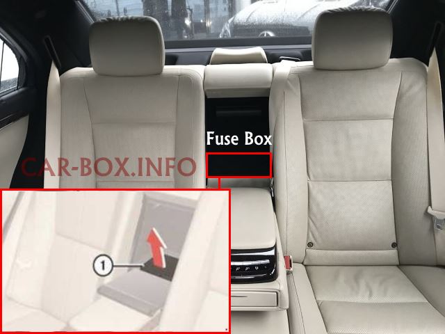
Access is from the passenger compartment. It is necessary to fold down the armrest. Then remove the trim and the plastic cover.
Access example.
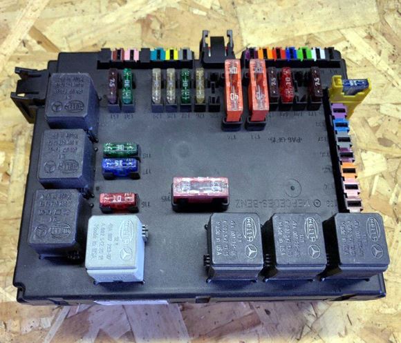
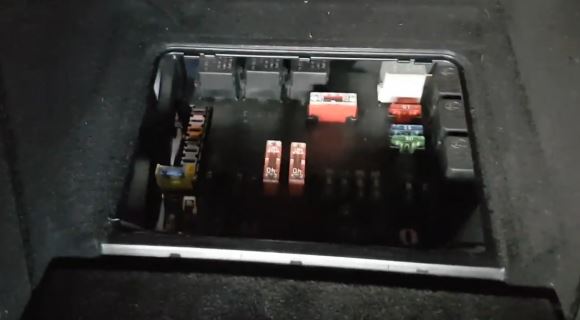
General view.
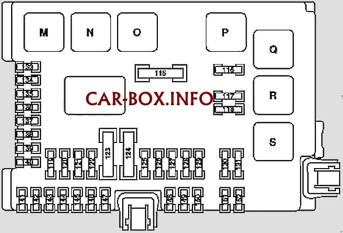
| Diagram | ||
|---|---|---|
|
||
| No. | Relay assignment | |
| M | Terminal 15 (2) / spare 1 (changeover relay) | |
| N | Terminal 15R | |
| O | Outlets | |
| P | Rear window heating | |
| Q | Motors 156, 157, 275, 278, 629: circulation pump | |
| S 400 Hybrid: Circulation pump relay 2 power electronic devices | ||
| R | Cigarette lighter relay | |
| S | Motors 642, except 642.8: fuel pump relay | |
| Motors 642.8, 651 from 1.6.2011: Refrigerant compressor solenoid clutch | ||
| S 400 Hybrid: Circulation pump relay 1 power electronic devices | ||
| No. | A | Purpose of fuses |
| 115 | 50 | Rear window heater |
| 116 | 10 | Engine 157, 275, 278: Charge air cooler circulation pump |
| Engine 156: Engine Oil Cooler Circulation Pump | ||
| S 400 Hybrid: Circulation pump 2 power electronic devices | ||
| 117 | 15 | Rear cigarette lighter fuse |
| 118 | 30 | Engine 629, 642: Fuel module (fuse for Mercedes W221 / C216 fuel pump) |
| 15 | S 400 Hybrid: Circulation pump 1 power electronic devices | |
| 15 | Motor 642.8, 651 from 1.6.2011: Refrigerant compressor with electromagnetic clutch | |
| 119 | 7.5 | Front center control panel |
| 120 | - | Reserve |
| 121 | 10 | Audio tuner module |
| 122 | 7.5 | COMAND module |
| 123 | 40 | W221: Front right reversible seat belt pretensioner |
| 124 | 40 | W221: Front left reversible seat belt pretensioner |
| 125 | 5 | Voice control module (SBS) |
| 126 | 25 | Overhead control panel |
| 127 | 30 | Lower backrest pump |
| Multicontour seat air pump | ||
| Pneumatic pump for dynamic seat adjustment | ||
| 128 | 25 | Engine 156, 157, 272, 273, 275, 276, 278, 642: Fuel pump control unit |
| 129 | 25 | UHI (Universal Cell Phone Interface) Module |
| 130 | 30 | Electric parking brake module |
| 131 | 7.5 | Antenna amplifier module above rear window |
| 133 | 15 | Trailer recognition module |
| 5 | Rear View Camera | |
| 134 | 15 | Luggage compartment socket |
| 135 | 7.5 | Radar Sensor Module (SGR) |
| PTS module (PARKTRONIC) | ||
| 136 | 7.5 | Engine 642.8: AdBlue ® control unit |
| 137 | 7.5 | From 1.9.10: Rear view camera |
| 138 | 5 | Navigation processor (Taiwan, up to 31.8.2010) |
| Emergency call system module | ||
| TV / tuner plug connection (Japan) | ||
| 139 | 15 | Refrigerated box in the rear seat backrest |
| 140 | 15 | Cigarette lighter plug connection with ashtray light, rearward |
| 115 V socket | ||
| 141 | 5 | Rear view camera control unit |
| Rear view camera power supply module | ||
| 142 | 7.5 | PTS module (PARKTRONIC) |
| Radar Sensor Module (SGR) | ||
| Video sensors and radar sensors module (from 1.9.10) | ||
| 143 | 25 | Rear seat module |
| 144 | 25 | |
| 145 | 20 | AHV trailer coupling, 13-pin |
| 146 | 25 | Trailer recognition system |
| 147 | - | Reserve |
| 148 | 25 | End coupling of terminal 30 of the panoramic sliding sunroof |
| 149 | 25 | Panoramic sliding sunroof control module |
| 150 | 7.5 | Combo TV tuner (analog / digital) |
| TV / tuner plug connection (Japan) | ||
| 151 | 20 | Trailer recognition system |
| 152 | 25 | DC / AC converter |
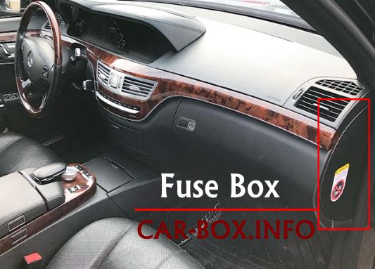
In the passenger compartment
There are three distribution boxes here, which are responsible for protecting the vehicle's electrical circuits.
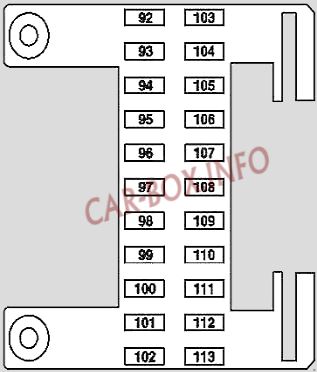
Fuse box No. 1

Located on the driver's side at the end of the instrument panel on the left side.
| Diagram | ||
|---|---|---|
|
||
| No. | A | Appointment |
| 92 | 40 | Front left seat module |
| 93 | 7.5 | Passive safety systems module |
| Passenger Weight System (WSS) Module (USA) | ||
| 94 | 5 | Multifunctional camera |
| 95 | - | Spare |
| 96 | 5 | RDK (Tire Pressure Monitoring System) |
| 97 | 7.5 | DVD-player |
| 98 | - | Spare |
| 99 | 7.5 | COMAND display |
| Display of the SPLITVIEW split image system | ||
| 10 | 5 | Multimedia interface control unit |
| 101 | 10 | W221: Rear display left and right |
| 102 | 40 | Front Right Seat Module |
| 103 | 7.5 | ESP |
| 104 | 40 | Audio tuner module |
| 105 | - | Spare |
| 106 | 5 | Navigation processor |
| Electronic Toll System (ETC) Module (Japan) | ||
| TV / tuner plug connection (South Korea) | ||
| 107 | 5 | SDAR module |
| Digital sound broadcasting module | ||
| High Definition Tuner Module | ||
| 108 | 5 | Rear air conditioner module |
| 109 | 15 | Rear air conditioning fan electronic regulator |
| 110 | 7.5 | Rear left and right rear seat control unit with multi-contour backrest |
| 111 | 5 | Rear control panel HBF |
| 112 | 5 | S 400 Hybrid: Front SAM control unit with fuse and relay module |
| 113 | 5 | S 400 Hybrid: DC / DC converter control unit |
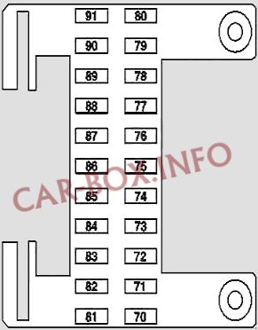
Fuse box No. 2
Located on the passenger side at the end of the instrument panel on the right side.
| Diagram | ||
|---|---|---|
|
||
| No. | A | Purpose of fuses |
| 70 | 40 | C216: Right door module |
| W221: Front right door module | ||
| 71 | 15 | KEYLESS-GO |
| 72 | 7.5 | S 400 Hybrid: Pyrotechnic disconnecting element |
| 73 | 5 | COMAND (Japan) |
| emergency call systems | ||
| 74 | 30 | HDS (trunk lid remote closing) |
| 75 | 10 | S 400 Hybrid: |
| Battery system unit | ||
| Power electronics control unit | ||
| 76 | - | Engine 642.8: AdBlue supply relay |
| 15 | S 400 Hybrid: Vacuum pump relay (+) | |
| 77 | 50 | Acoustic amplifier |
| 78 | 25 | S 65 AMG with 275 engine: Auxiliary fan relay |
| Engine 642.8: AdBlue supply relay | ||
| 15 | Engine 157, 278; S 400 Hybrid, CL 63 AMG: Charge air cooler circulation pump | |
| 79 | 7.5 | Alarm siren |
| 80 | 40 | C216: Left door module |
| W221: Front left door module | ||
| 81 | 30 | C216 Rear passenger compartment system module |
| 40 | W221: Rear left door module | |
| 82 | 30 | C216: Rear passenger compartment system module |
| 40 | W221: Rear right door module | |
| 83 | 30 | Servo drive module for automatic transmission system "DIRECT SELECT" |
| 84 | 20 | Digital sound processor |
| 85 | 10 | On AMG cars: Illuminated sill plates |
| 86-89 | - | Spare |
| 90 | 20 | C216: Heater STH (auxiliary heating system) |
| W221: Heater STH (autonomous) or ZUH (additional) | ||
| 91 | 5 | Receiving unit for radio remote control of the STH autonomous heater |
| S 400 Hybrid: Front SAM control unit with fuse and relay module | ||
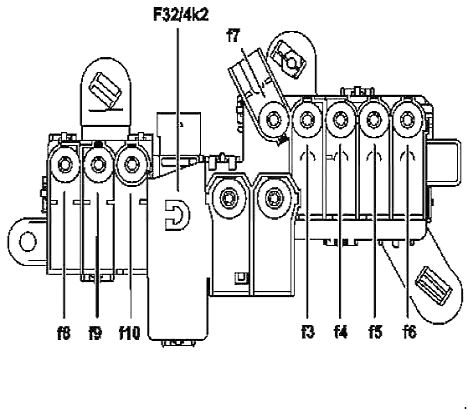
Power fusible links
Diagram of the elements of the power cabin block.
|
||
| No. | A | Appointment |
| 2 | 400 | Alternator (G2) |
| 3 | 150 | Electrohydraulic power steering system |
| Engine 629, 642: End of glow plug glow time | ||
| 4 | - | Passenger compartment fuse box F32 / 4 |
| 5 | 100 | Engine and air conditioning suction fan with integrated regulator |
| 6 | 150 | Front SAM control unit with fuse and relay module |
| 7 | 40 | ESP |
| S 400 Hybrid : Brake Energy Recovery Systems | ||
| 8 | 25 | ESP |
| S 400 Hybrid : Brake Energy Recovery Systems | ||
| 9 | 25 | Front SAM control unit with fuse and relay module |
| 10 | - | Spare |
| F32/4k2 - Standstill current trip relay | ||
In the engine compartment
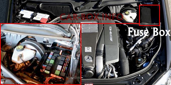
There are two distribution boxes here that are responsible for protecting the electrical circuits. Main #N10/1 is located on the left behind the protective cover.
Main fuse block
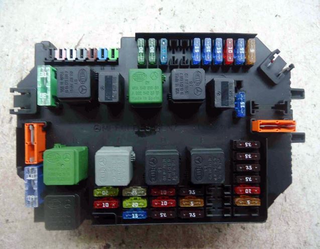
Photo - example of fuse box #N10/1.
| Diagram | ||
|---|---|---|

|
||
| No. | Relay | |
| A | Air pump | |
| B | Air suspension compressor | |
| C | Terminal 87 Engine | |
| D | Terminal 15 | |
| E | Relay of the electric circuit of terminal 87 of the running gear | |
| F | Horn relay | |
| G | Terminal 15R relay | |
| H | Relay circuit terminal 50, starter relay | |
| J | Relay circuit terminal 15, starter relay | |
| K | Heated wiper blades | |
| No. | A | Circuit breakers |
| 20 | 10 | Engine 629, 642, 651: CDI control unit |
| Engine 156, 157, 272, 273, 275, 276, 278: ME control unit | ||
| 21 | 20 | Engine 156, 157, 272, 273, 275, 276, 278: Electr. circuit terminal 87 M1i |
| Engine 629, 642: | ||
| CDI systems | ||
| Fuel pump relay Mercedes S-Class W221 / C216 | ||
| Engine 651: Metering valve | ||
| 22 | 15 | Engine 156, 157, 272, 273, 276, 278: Electr. terminal 87 circuit |
| 23 | 20 | Engine 156, 157, 272, 273, 275, 276, 278, 629, 642: Electr. terminal 87 circuit |
| Engine 156, 157, 272, 273, 276, 278: Electr. circuit terminal 87 M2e | ||
| Engine 275: Cable lug electr. circuit terminal 87 M2i | ||
| Engine 651: SAM with rear fuse and relay module | ||
| 24 | 25 | Engine 157, 272, 273, 276, 278: Electr. circuit terminal 87M1e |
| Engine 642: CDI control unit | ||
| 25 | 7.5 | Instrument cluster |
| 26 | 10 | Front left headlamp |
| 27 | 10 | Front right headlamp |
| 28 | 7.5 | Engine 275: |
| EGS module | ||
| Automatic gearbox integrated module (VGS) | ||
| 29 | 5 | Rear SAM control unit with fuse and relay module |
| 30 | 7.5 | Engine 629, 642, 651: CDI system module |
| Engine 156, 157, 272, 273, 275, 276, 278: | ||
| ME control module | ||
| Fuel pump module | ||
| 31 | 5 | S 400 Hybrid: Electric A / C Compressor |
| 32 | 15 | Gearbox auxiliary oil pump control unit |
| 33 | 5 | Since 1.9.10: ESP unit |
| S 400 Hybrid: | ||
| Battery control unit | ||
| DC voltage converter control unit | ||
| Power electronics control unit | ||
| 34 | 5 | S 400 Hybrid: Brake energy recovery control unit |
| 35 | 5 | Electric parking brake control unit |
| 36 | 10 | Diagnostic connector |
| 37 | 7.5 | EZS |
| 38 | 7.5 | Central interface control unit |
| 39 | 7.5 | Instrument cluster |
| 40 | 7.5 | Upper control panel |
| 41 | 30 | Slave wiper Engine |
| 42 | 30 | Main electric Engine of the cleaner |
| 43 | 15 | Front cigarette lighter fuse Mercedes-Benz S-Class W221 / C216 |
| 44 | - | Reserve |
| 45 | 5 | S 400 Hybrid: |
| Circulation pump 1 power electronics | ||
| 46 | 15 | ABC (Active Body Level Control) |
| AIRMATIC with ADS | ||
| 47 | 15 | Electric motor for steering column up and down adjustment |
| 48 | 15 | Electric motor for forward and reverse steering column adjustment |
| 49 | 10 | Steering column electronics |
| 50 | 15 | KLA control unit |
| 51 | 5 | COMAND display |
| Display of the SPLITVIEW split image system (split image system) | ||
| 52a | 15 | C216 Left and right horn (beep) |
| 52b | 15 | W221, C216: Left and right horn (beep) |
| 53 | - | Spare |
| 54 | 40 | Air recirculation unit for climate system |
| 55 | 60 | Gasoline Engines: Electric Air Pump |
| 56 | 40 | AIRmatic compressor block |
| 57 | 30 | Heated wiper blades |
| 60 | 5 | Electro-hydraulic power steering |
| 61 | 7.5 | passive safety system |
| 62 | 5 | night vision systems |
| 63 | 15 | With engine 629 and engine 642 from 1.9.2008: Fuel filter condensate sensor with heating element |
| 64 | 10 | NECK-PRO head restraint solenoid coil on the driver's seatback and right front seat backrest |
| 65 | 15 | Valid from 1.6.2009: 12 volt plug connection in the glove box |
| 66 | DTR control module (Distronic) | |
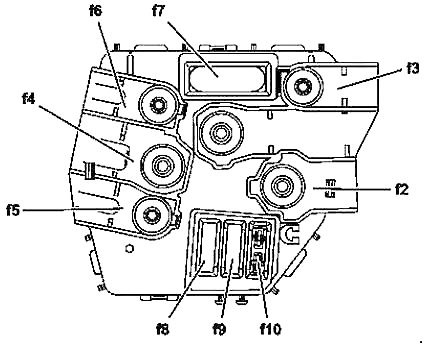
Power fusible links
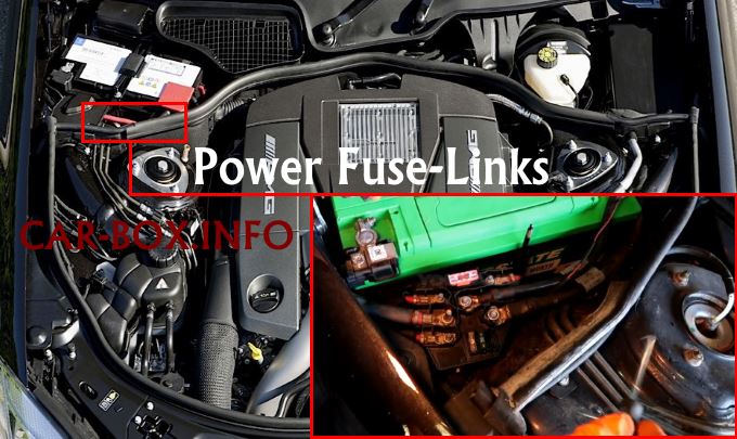
In the right side of the engine compartment, near the battery, there is a module consisting of high-power fusible links.
| Diagram | ||
|---|---|---|
|
||
| No. | A | Description |
| 3 | 150 | SAM with rear fuse and relay module |
| 4 | 150 | Relay for ECO Start-Stop function |
| S 400 Hybrid: DC / DC Converter Module | ||
| Heated windshield | ||
| 5 | 125 | Multifunctional vehicle control unit (MSS) |
| 40 | S 400 Hybrid : Vacuum pump | |
| 6 | 80 | Passenger compartment fuse box |
| 7 | 150 | Multifunctional Special Vehicle Control Module (MSS) |
| Engine 629, 642, 651: PTC auxiliary heater | ||
| 8 | 80 | Front SAM module with fuse and relay module |
| 9 | 80 | Passenger compartment fuse box, left |
| 10 | 150 | SAM with fuse and relay module in trunk |
