TThe S-Class in the W222 body premiered in May 2013. When creating the interior, its long-wheelbase version was taken as a basis for maximum comfort on the rear sofa. In 2017, the car went through a restyling. In this article, we will take a detailed look at the fuse box diagrams for the Mercedes W222 (6th Gen; S-Class: S300, S350, S400, S450, S500, S550, S560, S600, S650, S63, S65) 2013, 2014, 2015, 2016, 2017, 2018 and 2019, 2020 years of manufacture.

Here you will find the locations and photos of distribution boxes. The fuse responsible for the “cigarette lighter” is highlighted in bold.
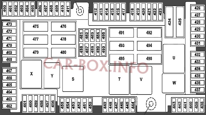
In the luggage compartment
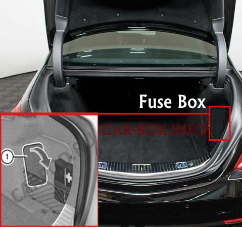
The distribution box is located in the right side of the trunk, behind the trim panel.
| Diagram | ||
|---|---|---|
|
||
| No. | A | Decryption |
| S | - | Relay circuit 15 |
| T | - | Rear window heater relay |
| U | - | cupholder and outlet relay in the back |
| V | - | Ad blue |
| W | - | circuit 15R |
| X | - | refrigerator and power outlets in the 1st row of seats |
| Y | - | Spare |
| 1 | - | Connection of circuit 30 "E1" |
| 2 | - | Circuit connection 30g "E2" |
| 400 | 10 | Parking system control unit (Active Parking Assist or 360-degree code camera) |
| 401 | 5 | Trunk lid control unit |
| 402 | 7.5 | Rear infotainment control unit |
| 403 | - | Spare |
| 404 | 7.5 | Armrest heater control unit |
| 405 | 7.5 | Sound system amplifier control unit / Front left door high-frequency speaker control unit / Front right door high-frequency speaker control unit |
| 406 | - | Spare |
| 407 | - | Spare |
| 408 | 5 | Tuner |
| 409 | 5 | 360 ° camera control unit |
| Rear View Camera | ||
| 410 | 5 | Camera cover control unit |
| 411 | 5 | tire pressure sensor |
| 412 | 7.5 | heated rear seat |
| 413 | 10 | Left rear display |
| Right rear display | ||
| 414 | 7.5 | Rear cellular telephone system antenna amplifier / compensator |
| Rear stand / mobile phone contact plate | ||
| Telephone module with Bluetooth® (SAP profile) | ||
| 415 | - | Reserve |
| 416 | - | Reserve |
| 417 | 20 | Trailer detection control unit |
| 418 | - | Reserve |
| 419 | - | Reserve |
| 420 | 30 | AC / DC converter control unit |
| 421 | 30 | Pneumatic pump with multi-circuit seat |
| 422 | 30 | W222: Right rear door control unit. |
| 423 | - | Reserve |
| 424 | 40 | Rear SAM unit |
| 425 | - | Reserve |
| 426 | 30 | Bass speaker booster |
| 427 | 20 | Armrest heater control unit |
| 428 | 15 | Trailer Recognition Control Unit |
| 429 | 10 | Rear cup holder |
| 430 | 15 | Mercedes 222 rear cigarette lighter fuse |
| 12 V socket on the rear left center console | ||
| 431 | 15 | Refrigerator in the back of the backrest |
| 432 | 10 | Rear SAM unit |
| 433 | 25 | Ad Blue® block |
| 434 | 15 | |
| 435 | 20 | |
| 436 | 20 | Rear cup holder |
| 437 | - | Reserve |
| 438 | 7.5 | C217 with 157 motor: right exhaust flap actuator. |
| 439 | 7.5 | C217 with 157 motor: left exhaust flap actuator. |
| 440 | - | Reserve |
| 441 | - | |
| 442 | - | |
| 443 | - | |
| 444 | - | |
| 445 | 5 | Stationary heater radio control receiver |
| 446 | 5 | Aerial amplifier FM 1, AM, CL [ZV] and KEYLESS-GO |
| 447 | 7.5 | Hybrid: battery management system control unit |
| 448 | - | Reserve |
| 449 | - | |
| 450 | - | |
| 451 | 15 | Trailer socket |
| 452 | 5 | Radar sensor for rear left bumper |
| Radar sensor for rear right bumper | ||
| Radar sensor for rear center bumper | ||
| 453 | 5 | Radar sensor for front left bumper |
|
||
| 454 | 5 |
|
| 455 | 15 | Fully integrated transmission control unit |
| 456 | - | Reserve |
| 457 | 7.5 | Valid for lithium-ion battery: starter battery capacitor |
| 458 | - | Reserve |
| 459 | - | Reserve |
| 460 | 15 | Front cigarette lighter fuse |
| 461 | 15 | 12 V socket on the rear right console / AC / DC converter control unit |
| 462 | 12V power outlet in the trunk | |
| 463 | Reserve | |
| 464 | 20 | Trailer Recognition Control Unit |
| 465 | 30 | Electric parking brake control unit |
| 466 | 30 | Front left door control unit |
| 467 | 10 | KEYLESS-GO module |
| 468 | 30 | Electric parking brake control module |
| 469 | 25 | Fuel system control module |
| 470 | 30 | Rear left seat heater control module |
| Rear seat heater control module | ||
| 471 | 30 | Rear Right Seat Heater Control Module |
| 472 | 30 | C217, A217: Rear control unit |
| 473 | 20 | Trailer recognition control module |
| 475 | 40 | Sound system amplifier control module |
| 476 | 40 | |
| 477 | 40 | Active belt buckle control module |
| C217, A217: Rear control unit | ||
| 478 | 30 | Left rear seat control module |
| 479 | 40 | Active Belt Buckle Control Module |
| 480 | 30 | Right rear seat control module |
| 481 | 5 | Reversible front left emergency tension retractor |
| 482 | 5 | W222: Control unit MAGIC SKY CONTROL |
| 482 | 7.5 | C217, A217: MAGIC SKY CONTROL control unit |
| 483 | 5 | Reversible front right retractor emergency tensioning mechanism |
| 484 | 7.5 | Right rear seat control module |
| Left rear seat control module | ||
| 485 | 5 | Active Belt Buckle Control Module |
| 486 | 10 | Hybrid: battery management system control unit, power electronics control unit |
| 487 | 5 | Electric parking brake control unit |
| 488 | 5 | Rear SAM unit |
| 489 | 5 | Front long-range radar sensor |
| 490 | 5 | Pneumatic pump with multi-circuit seat |
| 491 | 40 | Trunk lid control unit |
| 492 | 40 | Reversible front right retractor emergency tensioning mechanism |
| 493 | - | Reserve |
| 494 | 40 | Rear SAM unit |
| 495 | 40 | Rear window heater |
| 496 | 40 | Reversible front left emergency tension retractor |
In the passenger compartment
There are two distribution boxes here that are responsible for protecting the electrical circuits.
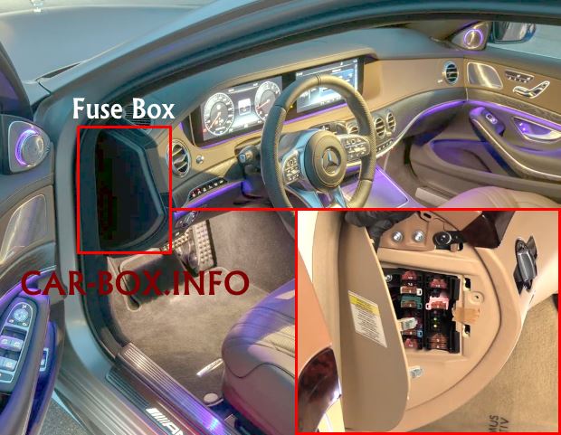
Primary fuse box
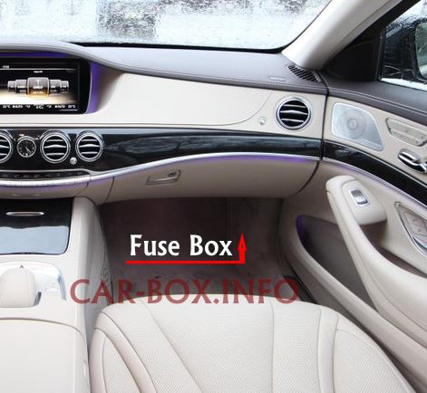
The main distribution box is located in the front passenger footwell.
General view of the Mercedes W222 / C217 interior fuse box.
| Diagram | ||
|---|---|---|

|
||
| No. | A | Description |
| 1 | Connection of circuit 30 "E1" | |
| 2 | Circuit connection 30g "E2" | |
| 301 | 5 | Mirror taximeter |
| 302 | 30 | Front right door control unit |
| 303 | 30 | W222: Rear left door control unit |
| C217, A217: Rear control unit | ||
| 304 | 30 | W222: Rear right door control unit |
| C217, A217: Rear control unit | ||
| 305 | 30 | Driver's seat control unit |
| 306 | 30 | Front passenger seat control unit |
| 307 | 20 | W222: Intelligent servo module for DIRECT SELECT |
| 307 | 30 | C217, A217: Driver's seat heater control unit. |
| 308 | 30 | Front passenger seat heater control unit |
| 309 | 5 | Emergency call control unit |
| Telematic services communication module | ||
| HERMES unit | ||
| 310 | 25 | Stationary heater control unit |
| 311 | 10 | Rear fan motor |
| 312 | 10 | Roof control panel control unit |
| 313 | 10 | Hybrid and Hybrid Plus: power electronics control unit |
| 314 | 7.5 | A217: Anti-theft alarm (designation by agreement) |
| 315 | 10 | Transmission control unit |
| Valid for gasoline engines: ME-SFI Unit | ||
| Valid for engines 642, 651: CDI Unit | ||
| 316 | - | Spare |
| 317 | 30 | W222: Control unit for panoramic sliding sunroof |
| C217, A217: MAGIC SKY CONTROL control unit | ||
| 318 | 15 | Audio / display COMAND |
| 319 | 30 | Panoramic sliding sunroof control unit |
| C217, A217: Panoramic sunroof control unit | ||
| 320 | 15 | Active Body Control / AIRmatic control unit (valid except Active Body Control) |
| 321 | 20 | C217, A217: Intelligent servo module for DIRECT SELECT |
| 322 | 15 | COMAND block |
| 323 | 7.5 | Control unit for the supplemental restraint system |
| MF1 / 1 | 7.5 | Japan version: special control unit for short-range communication system |
| MF1 / 2 | 7.5 | Multifunctional monaural camera |
| Multifunctional stereo camera | ||
| MF1 / 3 | 7.5 | Rain / light sensor with additional functions |
| Overhead control panel control unit | ||
| MF1 / 4 | 7.5 | Driver's seat control unit |
| MF1 / 5 | 7.5 | Front passenger seat control unit |
| MF1 / 6 | 7.5 | Steering column tube module control unit |
| MF2 / 1 | 5 | Perfume Atomizer Generator |
| MF2 / 2 | 5 | Audio control panel / COMAND |
| Touchpad | ||
| MF2 / 3 | 5 | Electronic stability system control unit |
| MF2 / 4 | 5 | Head-up display |
| MF2 / 5 | 5 | Hybrid and Hybrid Plus: Electric Refrigerant Compressor |
| MF2 / 6 | - | Reserve |
| MF3 / 1 | 5 | Front SAM unit |
| MF3 / 2 | 5 | Radar sensor control unit |
| MF3 / 3 | 5 | Fan motor COMAND |
| MF3 / 4 | 5 | Driver's side instrument panel button group |
| Button group of the central instrument panel | ||
| MF3 / 5 | 5 | Rear air conditioner control unit |
| MF3 / 6 | 5 | from 01.06.2016: Antenna switch for telephone and stationary heater |
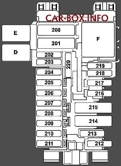
Auxilary fuse box
Located on the driver's side, at the end of the dashboard.
| Diagram | ||
|---|---|---|
|
||
| No. | A | Description |
| D | - | Relay MAGIC VISION CONTROL |
| E | - | Reserve |
| F | - | Relay circuit 15R |
| 200 | 40 | Front SAM module |
| 201 | 40 | |
| 202 | 5 | Alarm siren |
| 203 | 30 | W222: Driver's seat heater control unit. |
| 204 | 5 | Diagnostic connector |
| 205 | 7.5 | Electronic ignition switch control unit |
| 206 | 5 | Analog clock |
| 207 | 20 | Climate control |
| 208 | 7.5 | Instrument cluster |
| 209 | 5 | Front climate control |
| 210 | 10 | Steering column tube module control unit |
| 211 | - | Reserve |
| 212 | - | |
| 213 | 25 | Electronic stabilization system module |
| 214 | - | Reserve |
| 215 | - | |
| 216 | - | |
| 217 | 5 | Japanese version: special control unit for short-range communication system |
| 218 | 5 | Additional restraint system control unit |
| 219 | 5 | Weight Measurement System (WSS) |
| Recognizing front passenger seat occupancy and ACSR | ||
In the engine compartment
There are two distribution boxes here that are responsible for protecting the electrical circuits.
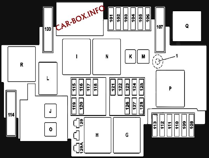
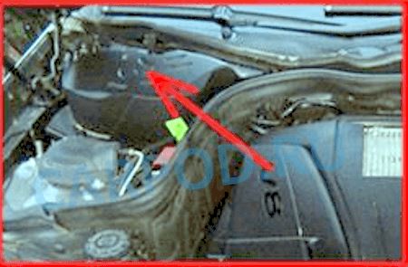
Fuse box
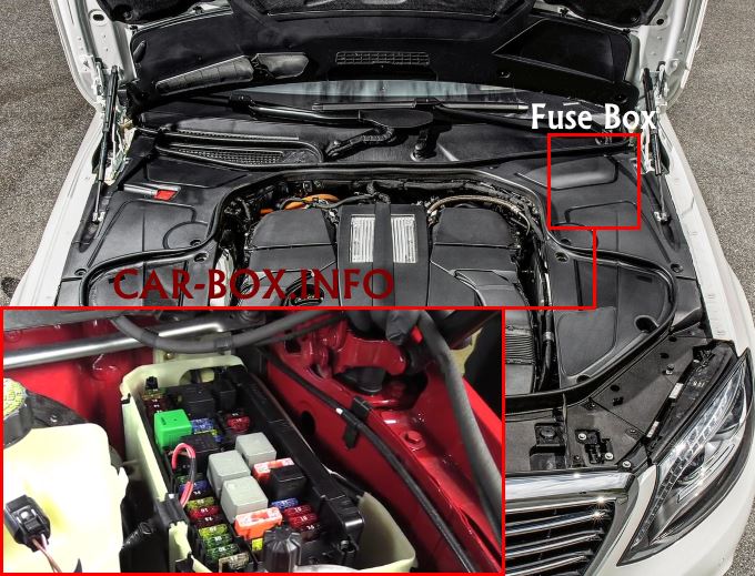
The engine fuse box is located on the left side of the underhood. To access it, remove the decorative plates, disconnect the wiring harnesses and remove the protective cover.
General view.
| Diagram | ||
|---|---|---|
|
||
| No. | Relay modules | |
| H | Engine compartment circuit 15 | |
| G | Starter circuit 50 | |
| I | Vacuum brake pump | |
| J | Hybrid: HYBRID relay | |
| K | Transmission oil pump | |
| L | Horn (beep) relay | |
| M | Wiper parking position heater relay | |
| N | Circuit 87M | |
| O | Except hybrid: starter circuit 15 relay | |
| P | Secondary air injection | |
| Q | Hybrid: vacuum pump relay | |
| R | AIRmatic relay | |
| No. | Purpose of fuses | A |
| 100 | Hybrid: vacuum pump | 40 |
| 101 | Coupling, circuit 87/2 | 15 |
| 102 | Coupling, circuit 87/2 | 20 |
| 103 | circuit coupling 87M4 | 15 |
| 104 | circuit coupling 87M3 | 15 |
| 105 | For gearbox 722.9: Transmission oil auxiliary pump control unit | 15 |
| 106 | Wiper parking position heater | 25 |
| 107 | Engine 277, 279: Starter / air pump electrical connection | 60 |
| 108 | Only with SAE dynamic LED headlamp for right-hand drive or dynamic LED headlamp: front left lamp unit, front right lamp unit. | 20 |
| Only without SAE dynamic LED headlight for right-hand drive or dynamic LED headlight: Front right lamp unit | ||
| 109 | Wiper motor | 30 |
| 110 | Only without LED headlight with SAE code for right-hand traffic or dynamic LED headlight: front left light, right front light. | 20 |
| Only without SAE dynamic LED headlight for right-hand drive or dynamic LED headlight: Front left lamp unit | ||
| 111 | Starter | 30 |
| 112 | Engine fuse and relay module | 5 |
| 113 | Spare | - |
| 114 | AIRmatic compressor | 40 |
| 115 | Left horn (beep) | 15 |
| Right horn (beep) | ||
| 116 | Hybrid: vacuum pump relay | 5 |
| 117 | Reserve | - |
| 118 | Hybrid: Electronic Stability Control Unit | 5 |
| 119 | Circuit Coupling 87 / C2 | 15 |
| 120 | Circuit Coupling 87 / C1 | 7.5 |
| 121 | Electronic stability control unit | 5 |
| 122 | Hybrid: HYBRID relay | 5 |
| 123 | Night View Assist control unit | 5 |
| 124 | Hybrid: electrical connector for vehicle interior and engine compartment | 5 |
| 125 | Front SAM unit | 5 |
| 126 | Transmission control unit | 5 |
| Diesel: CDI control unit | ||
| Gasoline: Control unit ME-SFI [ME] | ||
| 127 | Reserve | - |
| 128 | Outdoor light switch | 5 |
| 129A | Hybrid: 50 starter circuit relay | 30 |
| 129B | except hybrid: starter circuit relay 50 | 30 |
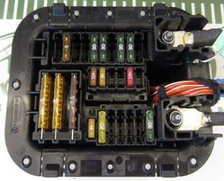
Power fuse panel
The power block, consisting of high-power fusible links, is located on the right side.
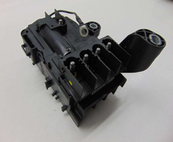
General view.
| Diagram | ||
|---|---|---|

|
||
| No. | A | Appointment |
| 1 | circuit 30 "B1" | |
| 2 | circuit 30 momentary "B2" | |
| M3 | 500 | Hybrid: electric car |
| M3 | 500 | Rome Hybrid: Alternator |
| M1 | - | Hybrid: electric car |
| M1 | - | except Hybrid: Starter |
| MR5 | 100 | Electric power steering unit |
| MR2 | 100 | Fan motor |
| M4 | 100 | Hybrid: fully integrated transmission control unit |
| I1 | - | Reserve |
| M2 | 150 | Diesel: glow plugs |
| MR1 | 60 | Engine fuse and relay module |
| MR3 | - | Reserve |
| MR4 | 150 | Engine 277, 279: Fan motor |
| I2 | - | Reserve |
