Fuso Canter is a series of compact medium-duty trucks, produced by Japanese company Mitsubishi Fuso Truck and Bus Corporation in different modifications since 1963. In this article, we will take a detailed look at the fuse box diagrams for the Mitsubishi Fuso Canter (seven generation) 2002, 2003, 2004, 2005, 2006, 2007, 2008, 2009, 2010 and 2011 years of manufacture.
Here you will find the locations and photos of distribution boxes. The fuses responsible for the “Cigarette lighter” and “Fuel Pump” are highlighted in bold.
The unit near the battery
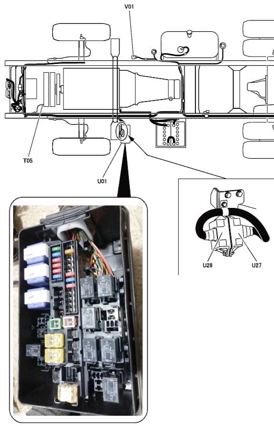
It is placed on the outside of the vehicle next to the battery.
| Diagram | ||
|---|---|---|

|
||
| № | Description | Amps |
| B25 | Rear lights | 15 |
| B26 | Rear fog lamps | 15 |
| B27 | Horn | 10 |
| B28 | Air conditioner | 5 |
| B29 | Air conditioner condenser fan | 15 |
| BZ0 | Air conditioner fan, heater fan | 15 |
| B33 | Fuel heater | 15 |
| B36 | Exhaust gas recirculation system engine / Engine control unit | 20 |
| FH1 | Fuse box (S1, A1-A4, M1-M12) | 60 |
| FH2 | Fuse Box (B1-B11) | 60 |
| FH3 | Fuse Box (B13-B16) | 30 |
| FH7 | ABS engine | 30 |
| FH8 | ABS electromagnetic switch | 30 |
| BATT1 | Alternator | 120 |
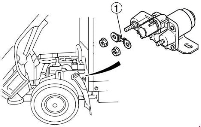
If the engine is equipped with a heating system and the indicator light does not illuminate in cold weather, check if the heating relay fuse (1) is blown. If it is blown, disconnect the lead (-) from the battery and replace the fuse with a new one.
In the passenger compartment
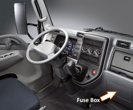
Located behind the dashboard trim. Remove the plastic cover to access it..
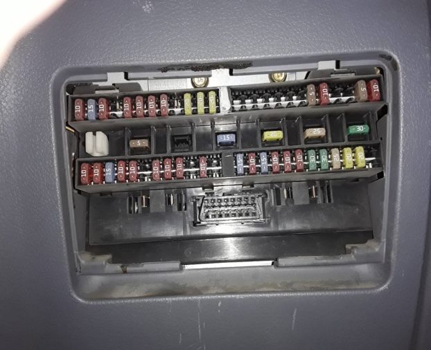
Access example.
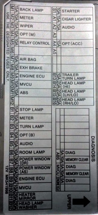
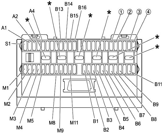
Example of a schematic from the block cover.
| Diagram | ||
|---|---|---|
|
||
| № | Description | Amps |
| A1 | Mitsubishi Fuso Canter cigarette lighter fuse | 10 |
| A2 | Audio | 10 |
| A4 | Additional power supply (ACC ignition switch) | 10 |
| IN 1 | Brake indicator lamp | 15 |
| IN 2 | Instrument cluster (EURO-3) Flow meter unit (EURO-4) | 10 |
| IN 3 | Turn signal lamps | 15 |
| AT 4 | Additional power supply (circuit directly connected to the battery) | 10 |
| AT 5 | Audio | 10 |
| AT 6 | Interior light | 10 |
| AT 7 | Power window elevator (driver) | 25 |
| AT 8 | Power window elevator (passenger) | 25 |
| AT 9 | ECU | 20 |
| AT 11 | Heated mirrors | 15 |
| B13 | Diagnostic connector | 15 |
| B14 | Headlights (high beam) | 15 |
| B15 | Left headlight (dipped beam) | 10 |
| B16 | Right headlight (dipped beam) | 10 |
| B25 | Rear lights | 15 |
| B26 | Rear fog lamps | 15 |
| B27 | Horn | 10 |
| B28 | Air conditioner | 5 |
| B29 | Air conditioner condenser fan | 15 |
| BZ0 | Air conditioner fan, heater fan | 15 |
| B33 | Fuel heater | 15 |
| B36 | Exhaust gas recirculation system engine / Engine control unit | 20 |
| M1 | Back-up lights | 10 |
| M2 | Instrument cluster (EURO-3) Flow meter unit (EURO-4) | 10 |
| M3 | Windscreen wiper and washer | 15 |
| M4 | Auxiliary power supply (ignition switch circuit is on) | 10 |
| M5 | Exhaust gas recirculation control relay | 10 |
| M8 | Exhaust brake | 10 |
| M9 | ECU | 5 |
| M11 | ABS | 10 |
| S1 | Starter | 10 |
| * | Spare | |
| 1 | ABS troubleshooting (diagnosis) | 5 |
| 2 | ABS troubleshooting (memory clearing) | 10 |
| 3 | Engine ECU troubleshooting (diagnostics) | 5 |
| 4 | Troubleshooting the engine ECU (memory clearing) | 10 |
General location of the electronic control units in the vehicle interior.
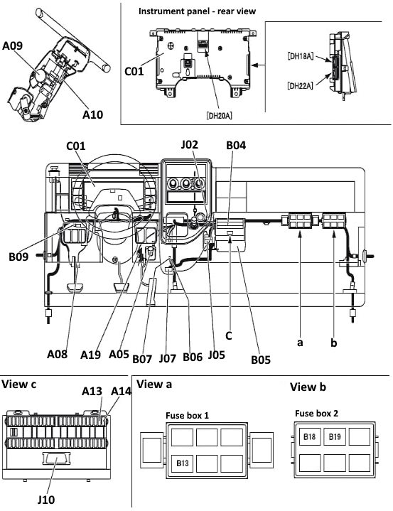
Description:
A05 - idle speed control potentiometer;
A08 - Clutch switch;
A09 - Starter switch;
A10 - switch combination;
A13 - diagnostic connector;
A14 - memory clearing connection;
A19 - Accelerator pedal position sensor;
C01 - instrument panel;
J02 - connector;
J10 - device connector Multifunction tester;
B04 - fuse box;
B05 - engine ECU;
B06 - diode;
B07 - CAN resistor;
B09 - resistor for fuel injection quantity control;
B13 - safety relay;
B18 - ABS emission cut-off relay;
B19 - glow plug relay.

hi hi need canter wirning daiagramm circiut help 2006 year 4m50 engine .