Outlander is a mid-size crossover produced by the Japanese Mitsubishi Corporation since 2001. The Outlander XL is based on two French cars, the Citroen C-Crosser and the Peugeot 4007, and is an almost complete copy of it. Were presented at the Geneva Motor Show in July 2007. In this article, we will take a detailed look at the fuse box diagrams for the Mitsubishi Outlander XL (second generation; codename CW0W) 2007, 2008, 2009, 2010, 2011, 2012 years of manufacture.

Here you will find the locations and photos of distribution boxes. The fuses responsible for the “Cigarette lighter” and “Fuel Pump” are highlighted in bold.
In the engine compartment
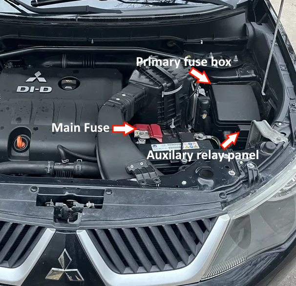
Location of components.
Main fuse
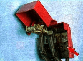
On the positive terminal of the battery there is a powerful fuse made in the form of fusible links.
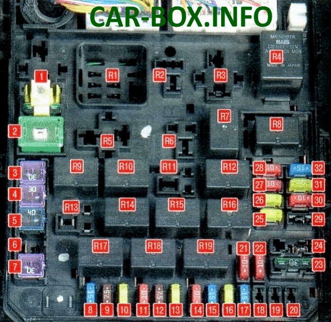
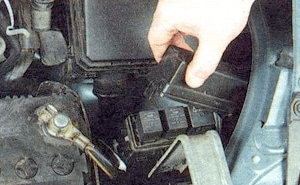
Primary fuse box
It is located behind the plastic cover on the left side.

Access example.
| Diagram | ||
|---|---|---|
|
||
| № | Description | A |
| R1 | Glow plug relay (for diesel engines) | |
| R2 | Radiator fan relay | |
| R3 | Heater relay | |
| R4 | Engine control relay | |
| R5 | Stability Relay | |
| R6 | A / C radiator fan relay | |
| R7 | Engine control relay | |
| R8 | Headlamp low beam relay | |
| R9 | Engine control relay | |
| R10 | Wiper heater relay | |
| R11 | daytime running light relay | |
| R12 | Engine control relay | |
| R13 | Anti-theft alarm relay | |
| R14 | Automatic transmission relay | |
| R15 | Headlight washer relay | |
| R16 | High beam relay | |
| R17 | Front fog lamp relay | |
| R18 | Horn relay | |
| R19 | Air conditioner relay | |
| 1 | I / O device | 30 |
| 2 | Cooling fan motor | 40 |
| 3 | Condenser fan motor | 30 |
| 4 | ABS | 30 |
| 5 | ABS | 40 |
| 6 | Spare | - |
| 7 | Starter | 30 |
| 8 | Front fog lamps | 15 |
| 9 | Engine management | 7.5 |
| 10 | automatic transmission | 20 |
| 11 | Horn | 10 |
| 12 | Alternator | 7.5 |
| 13 | Headlight washer | 20 |
| 14 | Air conditioner | 10 |
| 15 | Throttle valve | 15 |
| 16 | Anti-theft alarm sound | 20 |
| 17 | Heated windshield wiper blades | 15 |
| 18 | Spare | - |
| 19 | Electric trunk door | 30 |
| 20 | Daytime lighting system | 10 |
| 21 | High beam headlamp (left) | 10 |
| 22 | High beam headlamp (right) | 10 |
| 23 | Audio amplifier | 30 |
| 24 | Diesel engine electrical equipment | 30 |
| 25 | Left dipped beam headlamp (with discharge lamps) | 20 |
| 26 | Right dipped beam headlamp (with discharge lamps) | 20 |
| 27 | Left dipped beam headlamp (with halogen bulbs) | 10 |
| 28 | Right dipped beam headlamp (with halogen bulbs) | 10 |
| 29 | Engine power supply circuit | 10 |
| 30 | Ignition coil | 10 |
| 31 | Engine power supply circuit | 20 |
| 32 | Fuel pump fuse | 15 |
Auxilary relay panel
Located next to the main unit.

Description:
- R1 - Engine cooling fan low speed relay;
- R2 - Air conditioner fan relay;
- R3 - Engine cooling fan high speed relay.
In the passenger compartment

Located on the driver's side under the dashboard behind the storage box.

General view of the Mitsubishi Outlander XL 2 interior fuse box.
| Diagram | ||
|---|---|---|

|
||
| № | Description | Amps |
| 1 | Heater | 30 |
| 2 | Stop lights | 15 |
| 3 | Rear fog lamps | 10 |
| 4 | Windscreen wiper | 30 |
| 5 | Spare | - |
| 6 | Accessory circuit | 10 |
| 7 | Door locks | 20 |
| 8 | Audio system | 15 |
| 9 | Accessory circuit | 7.5 |
| 10 | Interior lamps | 15 |
| 11 | Hazard warning light | 15 |
| 12 | Rear door glass cleaner | 15 |
| 13 | Instrument cluster | 7.5 |
| 14 | Spare | - |
| 15 | Mitsubishi Outlander XL cigarette lighter fuse (front power outlet) | 15 |
| 16 | Ignition lock | 10 |
| 17 | sunroof | 20 |
| 18 | Spare | - |
| 19 | Exterior mirrors | 10 |
| 20 | All-wheel drive system | 10 |
| 21 | Back-up lights | 7.5 |
| 22 | Spare | - |
| 23 | Additional outlet | 15 |
| 24 | Power windows | 30 |
| 25 | Heated rear door glass | 30 |
| 26 | Heated exterior mirrors | 7.5 |
| 27 | Power supply | 15 |
| 28 | Power seat | 20 / 25 |
| 29 | Heated seats | 30 |
| R1 | Door lock relay | |
| R2 | Heater relay | |
| R3 | Seat heating relay | |
| R4 | Rear door window heater relay | |
