Pajero is a mid-size Japanese SUV, the flagship of Mitsubishi's model range. It was first presented in 1976 at the Tokyo Motor Show. In some foreign markets a different name was adopted. Thus, in Spain, India and America (except Brazil) it is called Montero, and in the UK it has the name Shogun. In this article, we will take a detailed look at the fuse box diagrams for the Mitsubishi Pajero / Montero / Shogun (second generation; V20 index) 1991, 1992, 1993, 1994, 1995, 1996, 1997, 1998, 1999, 2000 years of manufacture.

Here you will find the locations and photos of distribution boxes. Also, we will separately mark the fuse responsible for the cigarette lighter.
In engine compartment
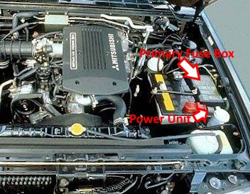
Location of components.
Power unit
Located on the positive terminal of the battery.
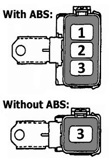
Description
1 - ABS 60A;
2 - Fog Lamps or not used 20A;
3 - Glow Plugs 80A;
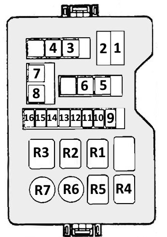
Primary fuse box
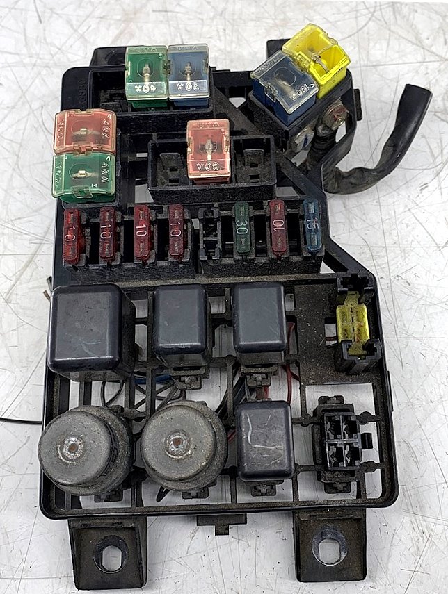
General view.
| Diagram | ||
|---|---|---|
|
||
| № | Description | Amps |
| 1 | Battery | 60 |
| 2 | Alternator | 100 |
| 3 | injection system | 20 |
| 4 | ignition switch | 40 |
| 5 | Rear window defogger | 30 |
| 6 | Power operated windows | 30 |
| 7 | Air conditioner | 30 |
| 8 | Lamps | 40 |
| 9 | Fuel heater | 15 |
| 10 | A / C compressor | 10 |
| 11 | Air conditioner condenser fan | 25 / 30 |
| 12 | Rear fog lamps | 10 |
| 13 | Taillights | 10 |
| 14 | Taillights | 10 |
| 15 | High beam headlights | 10 |
| 16 | Warning lights | 10 |
| 17 | ABS | 60 |
| 18 | Fog lights | 20 |
| 19 | Glow plug | 80 |
| R1 | Headlights | |
| R2 | Intercooler | |
| R3 | Alternator | |
| R4 | Rear fog lights | |
| R5 | Rear lights, parking lights | |
| R6 | Condenser fan motor | |
| R7 | Air conditioning compressor | |
In the passenger compartment
There are 2 blocks under the dashboard on the driver's side: the fuse box and the relay box.
Fuse box
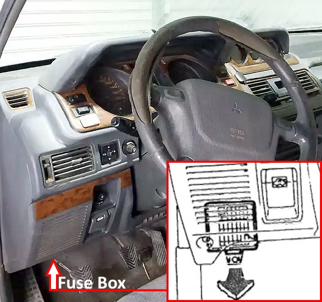
Located under the panel on the driver's side.
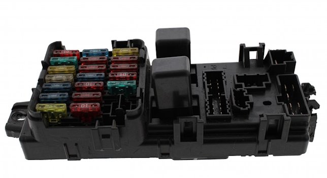
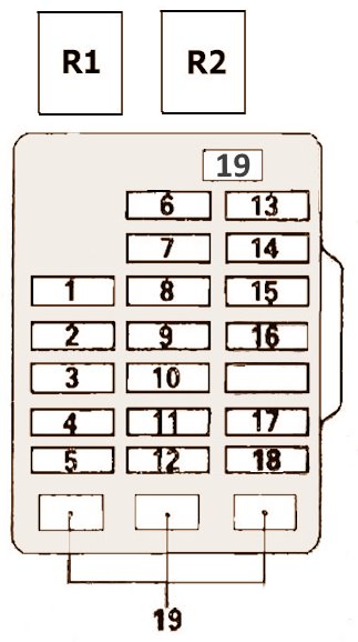
General view of the Pajero / Montero / Shogun interior fuse box.
| Diagram | ||
|---|---|---|
|
||
| # | Description | Amps |
| R1 | Accessory socket relay | |
| R2 | Heater fan relay | |
| 1 | Pajero / Montero / Shogun cigarette lighter fuse | 15 |
| 2 | Radio | 10 |
| 3 | Heater relay | 10 |
| 4 | Rear heater or ELC-4 A/T | 10 |
| 5 | Front and rear air conditioner | 20 |
| 6 | Turn indicator lamps | 10 |
| 7 | Meter | 10 |
| 8 | Horn | 10 |
| 9 | Wiper | 15 |
| 10 | Power window control unit | 10 |
| 11 | 4-wheel-drive system, Overdrive control (Vehicles with an automatic transmission only) | 10 |
| 12 | Electric door locks | 15 |
| 13 | Room lamps, Clock | 10 |
| 14 | Reverse light bulbs | 15 |
| 15 | Stop lamps | 15 |
| 16 | Heater | 25 |
| 17 | Accessory socket | 15 |
| 18 | Rear heater or Empty | 10 |
| 19 | Spare | |
Relay box
It is installed above the fuse box.
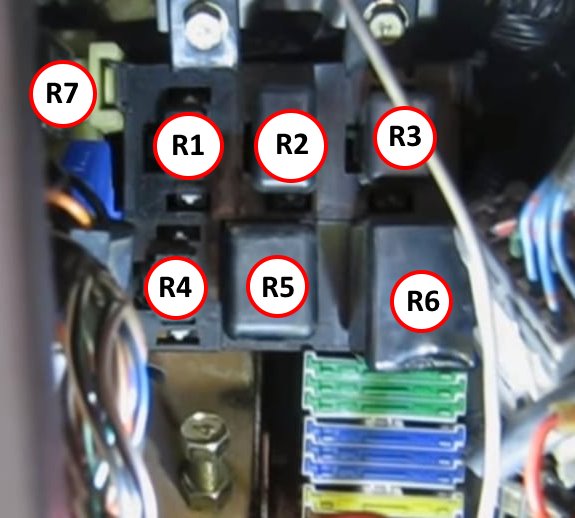
Description:
- R1 - Spare;
- R2 - Rear heater relay;
- R3 - Power window relay;
- R4 - Door central locking control unit;
- R5 - Heated rear window relay;
- R6 - Rear window wiper intermittent operation relay;
- R7 - Relay interrupter of direction indicators and signaling system.
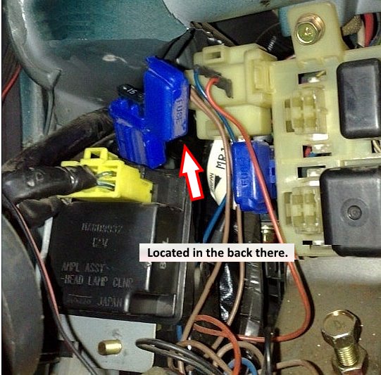
Individual fuses and relays can be installed outside the blocks, such as the fog light fuse.
