Pajero is a mid-size Japanese SUV, the flagship of Mitsubishi's model range. It was first presented in 1976 at the Tokyo Motor Show. In some foreign markets a different name was adopted. Thus, in Spain, India and America (except Brazil) it is called Montero, and in the UK it has the name Shogun. In this article, we will take a detailed look at the fuse box diagrams for the Mitsubishi Montero / Pajero / Shogun (fourth generation) 2007, 2008, 2009, 2010, 2011, 2012, 2013, 2014, 2015, 2016, 2017, 2018, 2019 years of manufacture.

Here you will find the locations and photos of distribution boxes. The fuses responsible for the “Cigarette lighter” and “Fuel Pump” are highlighted in bold.
In the engine compartment
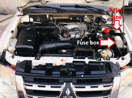
Location of components.
Fuse box
The main fuse and relay box is located next to the battery in the left side of the engine compartment.
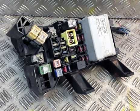
General view.
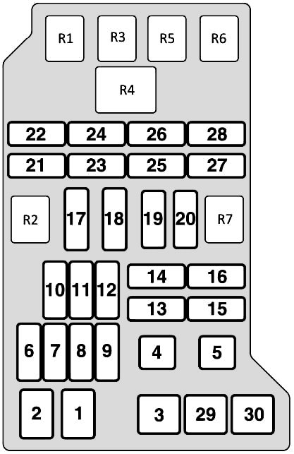
| Diagram | ||
|---|---|---|
|
||
| № | Description | Amps |
| 1 | Engine compartment fuse / relay box 1, fog lights, headlights, tail lights (2001), multi-function control unit 1 (2002 ^) | 120 |
| 2 | Fuse / relay box, engine compartment 1 | 60 |
| 3 | Ignition lock | 40 |
| 4 | Power seat, power windows | 40 |
| 5 | Engine control unit | 20 |
| 6 | Engine control unit | 20 |
| 7 | Empty | - |
| 8 | Optional equipment | 15 |
| 9 | Fuel filter heater | 25 |
| 10 | Air conditioner | 25 |
| 11 | Air conditioner | 20 |
| 12 | Windshield heater relay - Windshield wipers | 15 |
| 13 | Empty | - |
| 14 | automatic transmission | 20 |
| 15 | Alternator, central locking, turn signals / hazard warning lights | 10 |
| 16 | Anti lock brake system (ABS), brake lights | 15 |
| 17 | Audio system, cigarette lighter fuse, clock | 10 |
| 18 | Air conditioning, audio system, central locking, clock, ESP electronic control unit, interior lamps, multifunction control unit 1, transfer case control unit | 10 |
| 19 | Air conditioner | 10 |
| 20 | Fog lights | 20 |
| 21 | Buzzer | 10 |
| 22 | Windshield wiper / washer | 20 |
| 23 | Engine management system, tail lamp (right) | 10 |
| 24 | Lamp, left tailgate | 10 |
| 25 | Low beam (left) | 10 |
| 26 | Low beam lamp (right) | 10 |
| 27 | High beam lamp (left) | 10 |
| 28 | High beam lamp (right) | 10 |
| 29 | Empty | - |
| 30 | Coolant Heater | 40 |
| R1 | A / C Condenser Fan Motor Relay - High Speed | |
| R2 | Horn relay | |
| R3 | A / C Condenser Fan Motor Relay - Low Speed | |
| R4 | Multi-functional control unit 1 | |
| R5 | Heated windshield relay - windshield wipers | |
| R6 | A/C compressor solenoid clutch relay | |
| R7 | Spare | |
Relay box
Located behind the protective cover above the main unit.
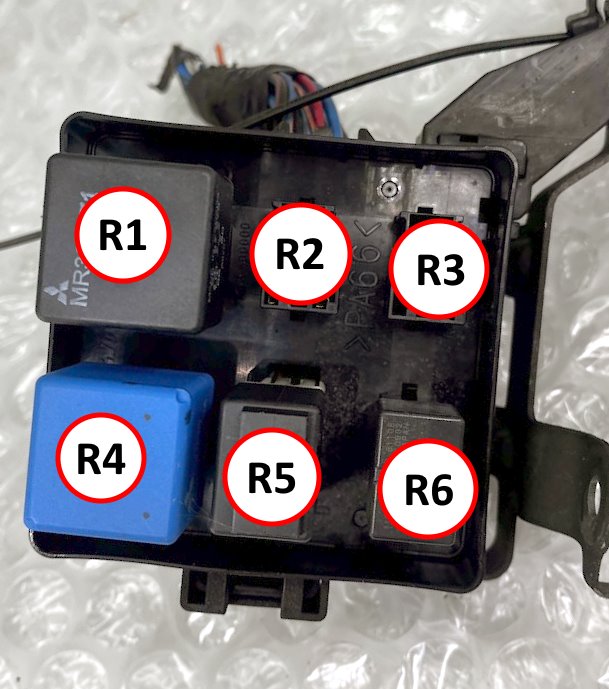
Description:
R1 - Solenoid valve relay;
R2 - Fuel heater relay;
R3 - Throttle servo relay;
R4 - Starter relay;
R5 - Injection system main relay;
R6 - A/C compressor solenoid clutch relay.
Separate fuses and relays may be installed outside the main units, such as the fuel pump motor relay or the ABS emergency braking system relay. Power fuses may also be located on the positive terminal of the battery: 40/60A - ABS and 80A - glow plugs.
In the passenger compartment
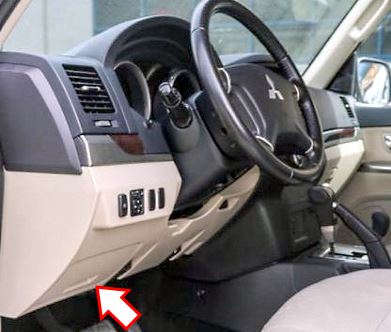
Located at the bottom of the instrument panel, behind the protective cover.
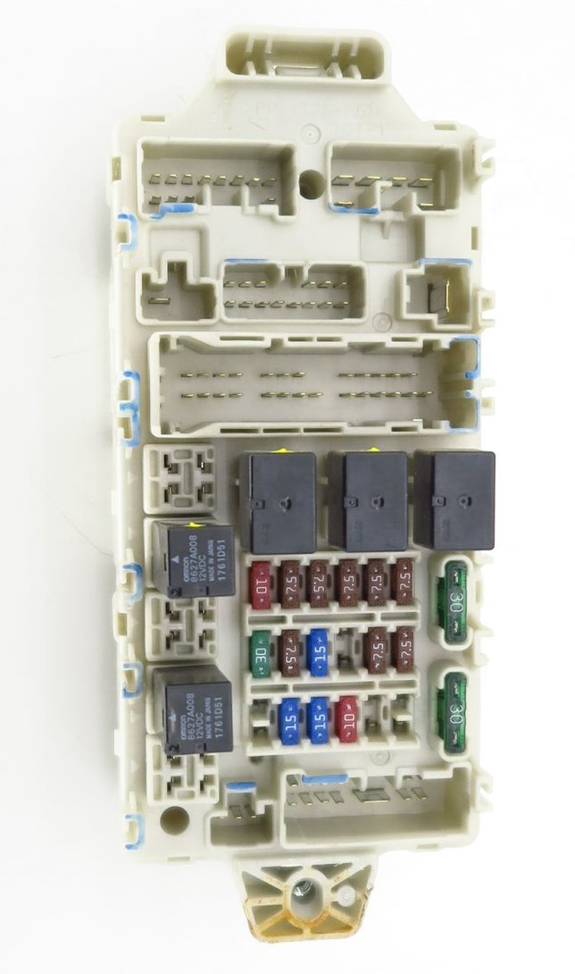
General view of the Mitsubishi Montero (Shogun) 4 interior fuse box.
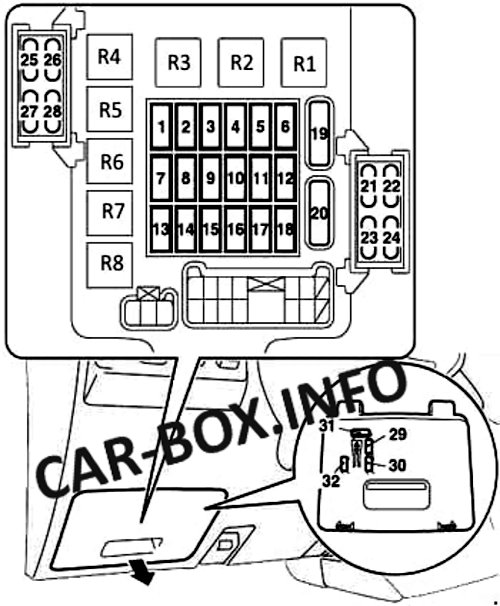
| Diagram | ||
|---|---|---|
|
||
| № | Description | Amps |
| R1 | Rear window defogger relay | |
| R2 | Front fan relay | |
| R3 | Power window relay | |
| R4 | Fuel pump relay 1 | |
| R5 | Rear fog lamp relay | |
| R6 | Fuel pump relay 2 | |
| R7 | relays for auxiliary power outlets | |
| R8 | Rear fan relay | |
| 1 | Ignition coils | 10 |
| 2 | Dashboard | 7,5 |
| 3 | Back-up lamps | 7,5 |
| 4 | Spare | 7,5 |
| 5 | Relay (heater, etc.) | 7,5 |
| 6 | Heated mirrors | 7,5 |
| 7 | Spare | 30 |
| 8 | Engine control unit | 7,5 |
| 9 | Cigarette lighter fuse | 15 |
| 10 | Empty | - |
| 11 | Power mirrors | 7,5 |
| 12 | Engine control unit | 7,5 |
| 13 | Empty | - |
| 14 | Rear wiper | 15 |
| 15 | Central locking | 15 |
| 16 | Rear fog lamp | 10 |
| 17 | Empty | - |
| 18 | Empty | - |
| 19 | Heater | 30 |
| 20 | Heated rear window | 30 |
| 21 | Sunroof | 20 |
| 22 | ABS | 10 |
| 23 | Heated seats | 20 |
| 24 | Lighting of steps and doorways | 10 |
| 25 | Transfer box control unit | 10 |
| 26 | ENG / POWER | 10 |
| 27 | Starter | 10 |
| 28 | Empty | - |
| 29 | Spare | 20 |
| 30 | Spare | 10 |
| 31 | Spare | 30 |
| 32 | Spare | 25 |
