The Outlander is a mid-size crossover produced by the Japanese Mitsubishi Corporation since 2001. Initially (when sales began in Japan) it was called Airtrek and was based on the ASX concept car shown at the 2001 North American International Auto Show. In this article, we will take a detailed look at the fuse box diagrams for the Mitsubishi Outlander 1 / Airtrek and Montero (first generation) 2001, 2002, 2003, 2004, 2005, 2006, 2007 and 2008 years of manufacture.

Here you will find the locations and photos of distribution boxes. The fuses responsible for the “Cigarette lighter” and “Fuel Pump” are highlighted in bold.
In the engine compartment
Under the hood there are three units responsible for the protection of the vehicle's electrical circuits.
Main fuse

The main fuse in the form of a fusible link is located on the positive terminal of the battery.
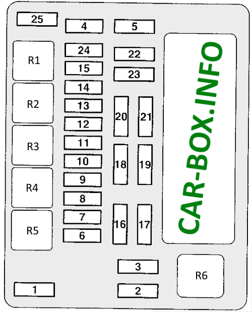
Primary fuse box
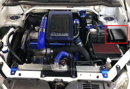
Installed on the left side of the engine compartment. Remove the protective cover to access it.

General view.
| Diagram | ||
|---|---|---|
|
||
| № | Amps / Description | A |
| 1 | Dashboard fuse / relay box | 60 |
| 2 | Cooling fan motor | 50 |
| 3 | ABS system | 60 |
| 4 | Ignition Lock Circuit | 40 |
| 5 | Power windows | 30 |
| 6 | Fog lights | 15 |
| 7 | Heated seats | 15 / 20 |
| 8 | Buzzer | 10 |
| 9 | Engine management system | 20 |
| 10 | A/C compressor solenoid clutch | 10 |
| 11 | Stop lights | 15 |
| 12 | Heated windshield | 15 |
| 13 | Generator | 7.5 |
| 14 | Alarm | 10 |
| 15 | Electronic transmission control unit | 20 |
| 16 | High beam, right headlight | 10 |
| 17 | High beam left headlight | 10 |
| 18 | Right dipped beam headlight | 10 |
| 19 | Left dipped beam headlight | 10 |
| 20 | Rear light (right) | 7.5 |
| 21 | Rear light (left) | 7.5 |
| 22 | Interior lamps | 10 |
| 23 | Audio system | 10 |
| 24 | fuel pump fuse | 15 |
| 25 | Accessory power connector | 15 |
| R1 | Spare | |
| R2 | Windshield heater relay | |
| R3 | Accessory power connector relay | |
| R4 | Horn relay | |
| R5 | Fog lamp relay | |
| R6 | Cooling fan motor relay | |
Auxilary relay panel
Diagram
 .
.
Description:
- Air conditioner compressor solenoid clutch relay;
- Engine control relay;
- Electronic transmission control unit relay;
- Ignition relay;
- Throttle control unit relay;
- Spare;
- Spare.
In the passenger compartment
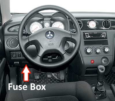
It is located on the driver's side behind the glove box at the bottom of the dashboard.
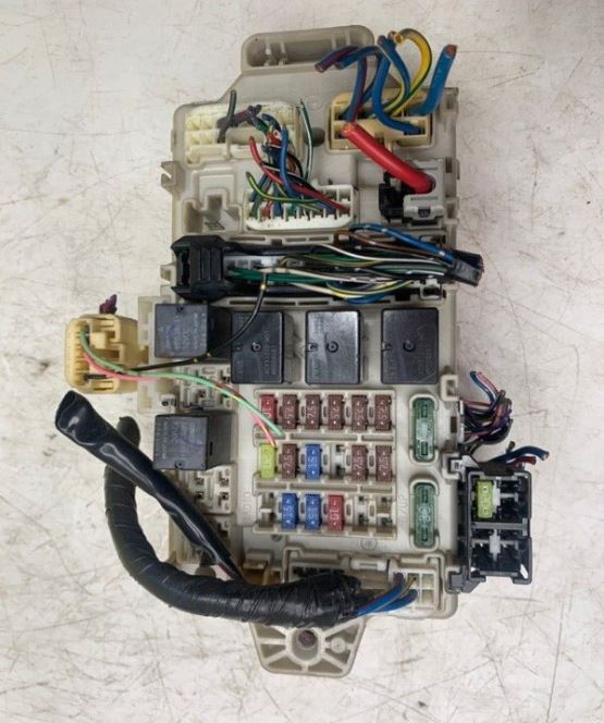
General view of the Mitsubishi Outlander 1 interior fuse box.
| Diagram | ||
|---|---|---|

|
||
| № | Description | Amps |
| 1 | Ignition system | 10 |
| 2 | Instrument cluster (panel) | 7.5 |
| 3 | Reversing lights, Automatic transmission control relay | 7.5 |
| 4 | Speed control system | 7.5 |
| 5 | Air conditioning system | 7.5 |
| 6 | Exterior mirror control panel | 7.5 |
| 7 | Cleaners and washers, Electronic lighting control unit | 20 |
| 8 | Electronic engine and automatic transmission control unit (for vehicles with automatic transmission), electronic engine control unit, fuel pump relay | 7.5 |
| 9 | Mitsubishi Outlander cigarette lighter fuse | 15 |
| 10 | Reserve | - |
| 11 | Power mirrors | 7.5 |
| 12 | ABS | 7.5 |
| 13 | Audio system, Radio | 10 |
| 14 | Rear window wiper / washer | 15 |
| 15 | Diagnostic connector | 15 |
| 16 | Rear fog lamp | 10 |
| 17 | Spare | - |
| 18 | Interior lamps | 10 |
| 19 | Heater blower motor | 30 |
| 20 | Heated rear window | 30 |
| 21 | Sunroof motor | 20 |
| 22 | Heated seats | 10 |
| 23 | Turbocharger intercooler cooling pump | 10 |
| 24 | Spare | - |
| R1 | Fuel pump relay (1) | |
| R2 | Heated front seat relay | |
| R3 | Fuel pump relay (2) | |
| R4 | Relay socket for connection of additional equipment | |
| R5 | Rear fog lamp relay | |
| R6 | Power window relay | |
| R7 | Heater fan motor relay | |
| R8 | Rear window heater relay | |
