The Lancer 10 was officially unveiled in January 2007 at the Detroit auto show and went on sale in the North American market in March of that year. This generation utilizes Mitsubishi's next-generation RISE safety body. An all-wheel drive version is available. In this article, we will take a detailed look at the fuse box diagrams for the Mitsubishi Lancer (ten generation; CY index) 2007, 2008, 2009, 2010, 2011, 2012, 2013, 2014, 2015, 2016, 2017 years of manufacture.
Here you will find the locations and photos of distribution boxes. The fuses responsible for the “Cigarette lighter” and “Fuel Pump” are highlighted in bold.
In the engine compartment
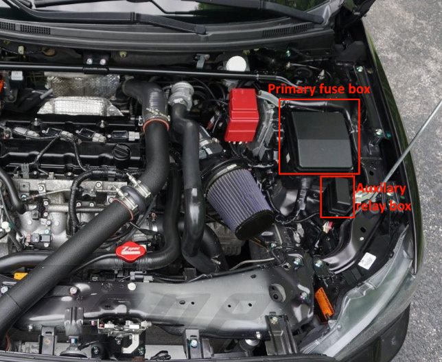
Location of components.
Power fuse box
On the positive terminal of the battery there is a powerful fuse block in the form of fusible links.

Appointment:
- 33 - fusible link No. 37 / fusible link Nos. 34-36 120A;
- 34 - Fuses #2, 4, 5, 10, 11, 12, 14, 15, 17, 18, 23, 24, 25 and #20 in the passenger compartment and ETACS-ECU 80A;
- 35 - Spare 80A;
- 36 - Fuses #1-23, 30-32 and fusible links #24-29 in engine compartment, engine control relay, headlight relay (high beam) and headlight relay (low beam) 120A;
- 37 - Fusible links nos. 1 and 21, fuses nos. 3, 6, 13, 16, 19, 22 in the passenger compartment, fan relay and ETACS-ECU. 80A.
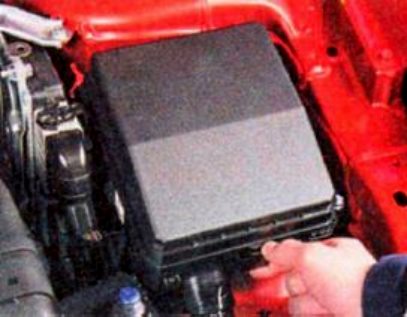
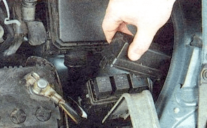
Primary fuse box
Mounted on left side of engine compartment.
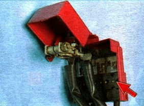
To gain access to the unit, press the latch.

And remove the distribution box cover.
| Diagram | ||
|---|---|---|

|
||
| № | Legend | Amps |
| 1 | I / O device | 30 |
| 2 | Cooling fan motor | 40 |
| 3 | Condenser fan motor | 30 |
| 4 | ABS | 30 |
| 5 | ABS | 40 |
| 6 | Spare | - |
| 7 | Starter | 30 |
| 8 | Front fog lamps | 15 |
| 9 | Engine control module | 7.5 |
| 10 | automatic transmission | 20 |
| 11 | Horn | 10 |
| 12 | Alternator | 7.5 |
| 13 | Headlight washer | 20 |
| 14 | Air conditioner | 10 |
| 15 | Throttle valve | 15 |
| 16 | Anti-theft alarm sound | 20 |
| 17 | Heated wiper blades | 15 |
| 18 | Spare | - |
| 19 | Electric trunk door | 30 |
| 20 | Daytime running lamps | 10 |
| 21 | High beam headlamp (left) | 10 |
| 22 | High beam headlamp (right) | 10 |
| 23 | Audio amplifier | 30 |
| 24 | Diesel engine electrical equipment | 30 |
| 25 | Left dipped beam headlamp (with discharge lamps) | 20 |
| 26 | Right dipped beam headlamp (with discharge lamps) | 20 |
| 27 | Left dipped beam headlamp (with halogen bulbs) | 10 |
| 28 | Right dipped beam headlamp (with halogen bulbs) | 10 |
| 29 | Engine power supply circuit | 10 |
| 30 | Ignition coil | 10 |
| 31 | Engine power supply circuit | 20 |
| 32 | Fuel pump fuse | 15 |
| R1 | Glow plug relay (for diesel engines) | |
| R2 | Radiator fan relay | |
| R3 | Heater relay | |
| R4 | Engine control relay | |
| R5 | Stability Relay | |
| R6 | A / C radiator fan relay | |
| R7 | Engine control relay | |
| R8 | Headlamp low beam relay | |
| R9 | Engine control relay | |
| R10 | Wiper heater relay | |
| R11 | Daytime running lights relay | |
| R12 | Engine control relay | |
| R13 | Anti-theft alarm relay | |
| R14 | Automatic transmission relay | |
| R15 | Headlight washer relay | |
| R16 | High beam relay | |
| R17 | Front fog lamp relay | |
| R18 | Horn relay | |
| R19 | Air conditioner relay | |
Auxilary relay box
Located next to the main one.
Diagram
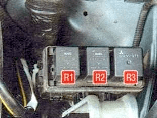
Description:
- R1 - Engine cooling fan low speed relay;
- R2 - Air conditioner fan relay;
- R3 - Engine cooling fan high speed relay.
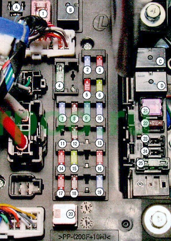
In the passenger compartment
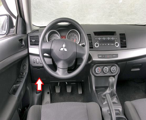
Located under the dashboard on the driver's side, behind a protective cover.
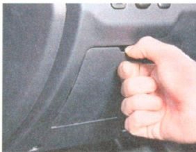
To access the fuse box located in the passenger compartment, remove the cover by overcoming the elastic resistance of the latches.
| Diagram | ||
|---|---|---|
|
||
| No. | Decoding | A |
| 1 | Heater (fusible link) | 30 |
| 2 | Brake lights | 15 |
| 3 | Rear fog light | 10 |
| 4 | Windshield wiper | 30 |
| 5 | Auxiliary circuits | 10 |
| 6 | Electric door locks | 20 |
| 7 | Audio system | 15 |
| 8 | Control unit relay | 7.5 |
| 9 | Interior light bulbs (lamps) | 15 |
| 10 | Hazard warning lights | - |
| 11 | Rear window wiper | 15 |
| 12 | Instrumentation | 7.5 |
| 13 | Lancer 10 cigarette lighter fuse / power socket | 15 |
| 14 | Egnition lock | 10 |
| 15 | Sunroof | 20 |
| 16 | Exterior mirrors | 10 |
| 17 | All-wheel drive system | 10 |
| 18 | Back-up lights | 7.5 |
| 19 | Power outlet | 15 |
| 20 | Power windows (fusible link) | 30 |
| 21 | Heated rear window (fusible link) | 30 |
| 22 | Heated exterior mirrors | 7.5 |
| 23 | AC power supply | 15 |
| 24 | Power seats | 25 (20) |
| 25 | Seat heating | 30 |
| Relay | ||
| A | Optional equipment | |
| B | Heater fan relay | |
| C | seat heating | |
| D | heated rear window | |
