The third generation was presented in March 2012 at the Geneva Motor Show. In 2012, they announced the possible appearance of a plug-in hybrid, which would be powered by electric traction in conjunction with a gasoline engine. It was named the Outlander P-HEV. Sales began in late 2013. In this article, we will take a detailed look at the fuse box diagrams for the Mitsubishi Outlander P-HEV (third generation; GF0W, GG0W index) 2012, 2013, 2014, 2015, 2016, 2017, 2018, 2019, 2020 years of manufacture.
Here you will find the locations and photos of distribution boxes. The fuses responsible for the “Cigarette lighter” and “Fuel Pump” are highlighted in bold.
In the engine compartment
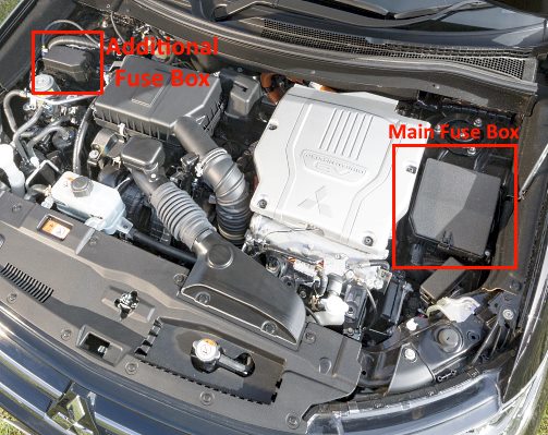
Location of components.
Battery-powered unit
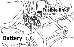
On the positive terminal of the battery is placed the main unit, made in the form of powerful fusible links.
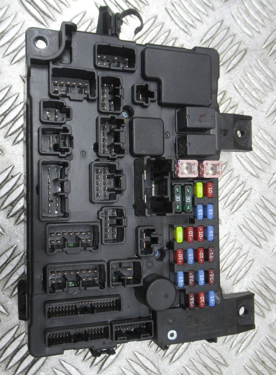
Main fuse box
Installed on the left side.
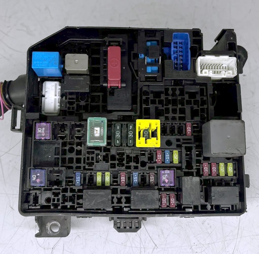
General view.
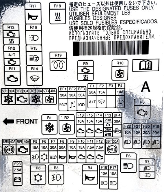
Example of a schematic from the block cover.
| Diagram | ||
|---|---|---|
|
||
| № | Description | Amps |
| SBF1 | Condenser fan motor | 30 |
| SBF2 | Starter | 30 |
| SBF3 | Condenser fan motor | 30 |
| SBF4 | Engine cooling fan motor | 40 |
| SBF5 | ABS | 40 |
| SBF6 | VLC | 40 |
| SBF7 | ABS | 30 |
| BF1 | Electric tailgate | 30 |
| BF2 | Audio amplifier | 30 |
| BF3 | Input-output device | 30 |
| BF4 | Diesel engine electrical equipment | 30 |
| 1 | automatic transmission | 20 |
| 2 | Heated wiper blades | 15 |
| 3 | Spare | - |
| 4 | Daytime running lights | 10 |
| 5 | Fog lights | 15 |
| 6 | Air conditioner | 10 |
| 7 | Headlight washers | 20 |
| 8 | Anti-theft alarm sound | 20 |
| 9 | Horn | 10 |
| 10 | Throttle valve actuator | 15 |
| 11 | Alternator | 7.5 |
| 12 | Engine control module | 7.5 |
| 13 |
|
20 / 25 |
| 14 | Petrol fuel pump fuse | 15 |
| 15 | Ignition coil | 10 |
| 16 | Engine power supply circuit | 10 |
| 17 | High beam headlamp (left) | 10 |
| 18 | High beam headlamp (right) | 10 |
| 19 | With discharge lamp: Dipped-beam headlamp (left) | 20 |
| 20 | With discharge lamp: Dipped-beam headlamp (right) | 20 |
| 21 | With halogen bulb: Dipped beam headlamp (left) | 10 |
| 22 | With halogen bulb: Dipped beam headlamp (right) | 10 |
| 23 | Battery charge sensor | 7.5 |
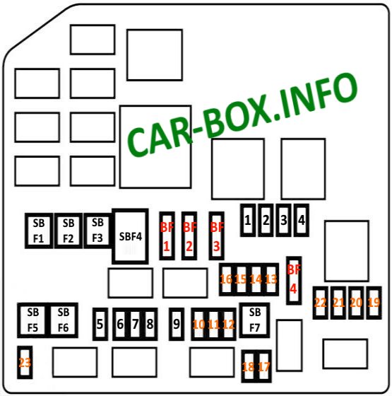
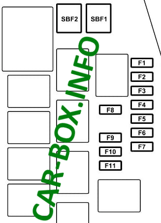
Additional fuse box
Installed on the right side.
| Diagram | ||
|---|---|---|
|
||
| № | Description | A |
| SBF1 | Chamber | 30 |
| SBF2 | Vacuum pump | 30 |
| F1 | Water pump (electric motors) | 20 |
| F2 | Battery Management | 7.5 |
| F3 | Heater Power Battery | 15 |
| F4 | Fuel filler flap | 7.5 |
| F5 | air conditioning solenoid | 7.5 |
| F6 | Air conditioning pump | 7.5 |
| F7 | Electric motor controller | 10 |
| F8 | Heated windshield | 7.5 |
| F9 | Main Battery Driver / Power Supply & Charge Controller | 15 / 10 |
| F10 | Ignition controller | 15 |
| F11 | Ignition controller | 7.5 |
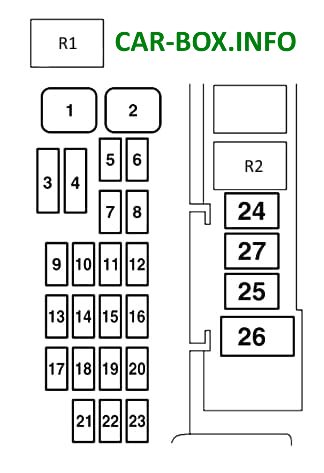
In the passenger compartment
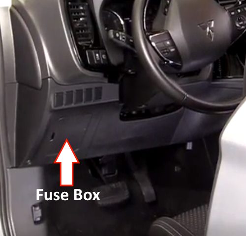
It is located on the driver's side under the dashboard behind a plastic cover.
General view of the Mitsubishi Outlander 3 interior fuse box.
| Diagram | ||
|---|---|---|
|
||
| № | Description | A |
| 1 | Power windows | 30 |
| 2 | Rear window heated | 30 |
| 3 | Heater | 30 |
| 4 | Windshield wiper | 30 |
| 5 | Electric door locks | 20 |
| 6 | Rear fog lamp | 10 |
| 7 | Power outlet | 15 |
| 8 | Rear window wiper | 10 |
| 9 | Sunroof | 20 |
| 10 | Ignition lock | 10 |
| 11 | Options | 10 |
| 12 | Hazard warning lights | 15 |
| 13 | All-wheel drive system | 10 |
| 14 | Stop lights (brake lights) | 15 |
| 15 | Instrument panel | 10 |
| 16 | SRS airbag system | 7.5 |
| 17 | Audio system | 15 |
| 18 | Relay control unit | 7.5 |
| 19 | Interior lamps (lampshades) | 15 |
| 20 | Reverse lights (reversing lamps) | 7.5 |
| 21 | Heated exterior mirrors | 7.5 |
| 22 | Exterior mirrors | 10 |
| 23 | Outlander 3 PHEV Cigarette Lighter Fuse / Power Outlet | 15 |
| 24 | Charge system | 7.5 |
| 25 | Power seat | 30 |
| 26 | Heated seats | 30 |
| 27 | Spare | - |

In the title are fuses and relays but I can not see the list of relays and relays on the pictures. the information you provided is in the manual. I can not find the info about relays. Which one is horn relay?
what number is the low beam relay on a 2017 Mitsubishi Outlander with Halogen headlights?
My Charging cable (New) stopped working on 2015 PHEV Has it goany fuses or relays?