In spring 2000, Mitsubishi Lancer in CS body was presented in Japan, which received its own name Cedia. In 2003 the model received a deep facelift. In this article, we will take a detailed look at the fuse box diagrams for the Mitsubishi Lancer (ninth generation) 2001, 2002, 2003, 2004, 2005, 2006 and 2007 years of manufacture.

Here you will find the locations and photos of distribution boxes. The fuses responsible for the “Cigarette lighter” and “Fuel Pump” are highlighted in bold.
In the engine compartment
Under the hood there are three units responsible for the protection of the vehicle's electrical circuits.
Main fuse

The main power fuse in the form of a powerful jumper is located on the positive terminal of the battery.
Primary fuse box
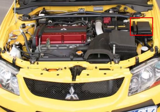
Installed on the left side of the engine compartment. It consists of the main fuse box and auxiliary relay panel.
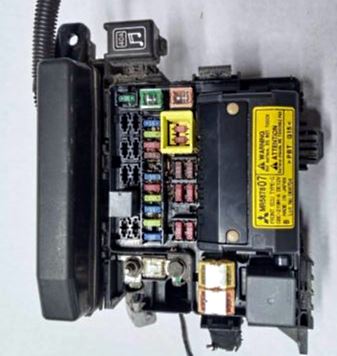
General view.
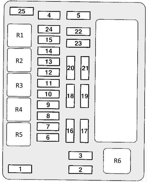
| Diagram | ||
|---|---|---|
|
||
| № | Description | Amps |
| 1 | Dashboard Fuse / Relay Box 80A Battery | 60 |
| 2 | Cooling fan motor | 50 |
| 3 | ABS system | 60 |
| 4 | Ignition interlock circuit | 40 |
| 5 | Power windows | 30 |
| 6 | Fog lights | 15 |
| 7 | Heated seats | 15 / 20 |
| 8 | Buzzer | 10 |
| 9 | Engine management system | 20 |
| 10 | A/C compressor solenoid clutch | 10 |
| 11 | Stop lights | 15 |
| 12 | Heated windshield | 15 |
| 13 | Generator | 7.5 |
| 14 | Alarm | 10 |
| 15 | Electronic transmission control unit | 20 |
| 16 | High beam, right headlight | 10 |
| 17 | High beam left headlight | 10 |
| 18 | Right dipped beam headlight | 10 |
| 19 | Left dipped beam headlight | 10 |
| 20 | Rear light (right) | 7.5 |
| 21 | Rear light (left) | 7.5 |
| 22 | Interior lamps | 10 |
| 23 | Audio system | 10 |
| 24 | fuel pump fuse | 15 |
| 25 | Accessory power connector | 15 |
| Relay designation: R1. Spare. R2. Windshield heater relay R3. Accessory Power Connector Relay R4. Horn relay R5. Fog lamp relay R6. Cooling fan motor relay |
||
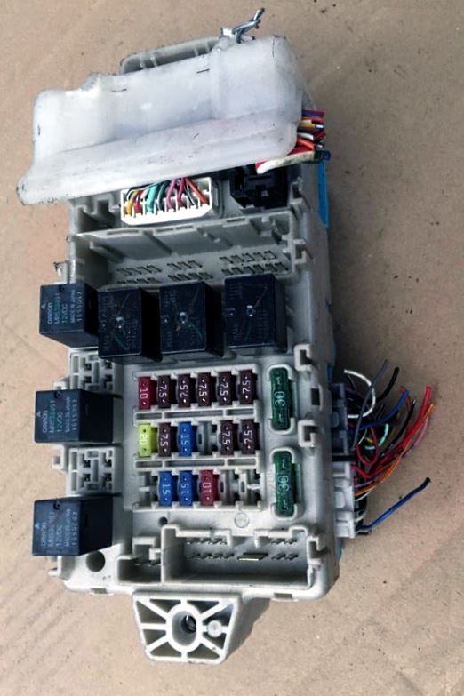
Auxilary relay panel
Diagram

Description
- A/C compressor solenoid clutch relay;
- Engine control relay;
- Electronic transmission control unit relay;
- Ignition relay;
- Throttle control unit relay;
- Spare;
- Spare.
In the passenger compartment

It is located on the driver's side behind the change storage box.
General view of the Mitsubishi Lancer 9 interior fuse box.
| Diagram | ||
|---|---|---|

|
||
| № | Amps / Description | A |
| 1 | Ignition system | 10 |
| 2 | Instrument cluster (panel) | 7.5 |
| 3 | Reverse lights, automatic transmission control relay | 7.5 |
| 4 | Speed control system | 7.5 |
| 5 | Air conditioning system | 7.5 |
| 6 | Control panel for exterior mirrors | 7.5 |
| 7 | Cleaners and washers, Electronic lighting control unit | 20 |
| 8 | Electronic engine and automatic transmission control unit (for vehicles with automatic transmission), electronic engine control unit, fuel pump relay | 7.5 |
| 9 | Lancer 9 cigarette lighter fuse | 15 |
| 10 | Spare | - |
| 11 | Power mirrors | 7.5 |
| 12 | ABS | 7.5 |
| 13 | Audio system, Radio | 10 |
| 14 | Rear window wiper / washer | 15 |
| 15 | Diagnostic connector | 15 |
| 16 | Rear fog lamp | 10 |
| 17 | Spare | - |
| 18 | Interior lamps | 10 |
| 19 | Heater blower motor | 30 |
| 20 | Heated rear window | 30 |
| 21 | Sunroof motor | 20 |
| 22 | Heated seats | 10 |
| 23 | Turbocharger intercooler cooling pump | 10 |
| 24 | Spare | - |
| R1 | Fuel pump relay (1) | |
| R2 | Heated front seat relay | |
| R3 | Fuel pump relay (2) | |
| R4 | Relay socket for connection of additional equipment | |
| R5 | Rear fog lamp relay | |
| R6 | Power window relay | |
| R7 | Heater fan motor relay | |
| R8 | Rear window heater relay | |

many thanks
Thank you