The 1st generation Nissan Juke mini crossover was produced in 2010, 2011, 2012, 2013, 2014, 2015, 2016, 2017, 2018, 2019 and 2020. At present, the 2nd generation of the model has arrived for assembly. The 2014 update had a lot to do with the look. In our material, we will show where the Nissan Beetle fuse and relay blocks are located, their photos, diagrams and a description of the purpose of the elements, we separately note the cigarette lighter fuse.

General arrangement
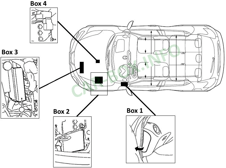
The Nissan Juke has 4 blocks with fuses and relays. One in the cabin and 3 under the hood. Their location is shown in the diagram.
In the passenger compartment
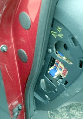
This block, number 1 in the diagram, is located at the end of the dashboard, behind the protective cover.
| Diagram | |
|---|---|
|
|
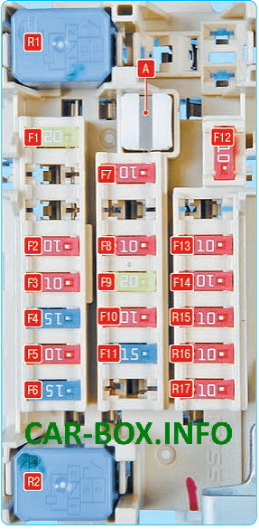
| № | Description |
| F1 | 20A Socket for connecting additional equipment, cigarette lighter, audio system, electric drive of outside rear-view mirrors |
| F2 | 10A Audio system |
| F3 | 10A Mounting block in the engine compartment |
| F4 | 15A Blower fan relay |
| F5 | 10A Air conditioner |
| F6 | 15A Blower fan relay |
| F7 | 10A Optional equipment |
| F8 | 10A Instrument cluster |
| F9 | 20A Trailer electrical equipment |
| F10 | 10A Interior lighting plafond |
| F11 | 15A Heated seats |
| F12 | 10A Heated exterior mirrors |
| F13 | 10A Instrument cluster |
| F14 | 10A Optional equipment |
| F15 | 10A Optional equipment |
| F16 | 10A Washers |
| F17 | 10A Passive Restraint System (SRS) |
| R1 | Relay additional equipment of salon |
| R2 | Blower fan relay |
In the engine compartment
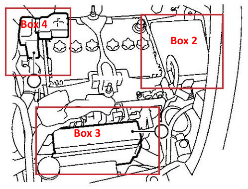
Fuse Box #2
It is numbered 2 in the diagrams.
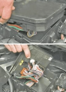
Located at the very edge of the motor space. To access it is necessary to remove the air filter sleeve.
| Diagram | |
|---|---|
|
|
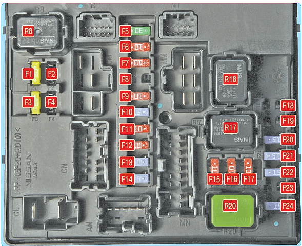
| № | Description |
| F1 | 20A Heated rear door glass, heated rear-view mirrors |
| F2 | Not used |
| F3 | 20A Engine management system |
| F4 | Not used |
| F5 | 30A Windshield wiper, wipers |
| F6 | 10A Right marker lamps |
| F7 | 10A Left marker lamps |
| F8 | Not used |
| F9 | 10A A / C compressor clutch |
| F10 | 15A Fog lights |
| F11 | 10A High beam lamps, right headlights |
| F12 | 10A High beam lamps, left headlights |
| F13 | 15A Low beam lamps, left headlights |
| F14 | 15A Low beam lamps, right headlights |
| F15 | 10A Engine management system |
| F16 | 10A Reversing lamp |
| F17 | 10A Anti-lock braking system |
| F18 | Not used |
| F19 | Not used |
| F20 | 15A Fuel pump |
| F21 | 15A Ignition system |
| F22 | 15A injection system |
| F23 | Not used |
| F24 | 15A Power steering |
| R8 Rear door heater relay R17 Relay for lowering (-) revolutions of the cooling fan R18 Relay for increasing (+) revolutions of the cooling fan R20 Ignition system relay |
|
Fuse Box #3
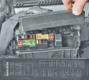
It is designated by number 3. To gain access to the fuses of the block on the casing of the electronic engine control unit, squeeze the cover latch. On the inner side of which, the current layout of the elements will be applied.
| Diagram | |
|---|---|
|
|
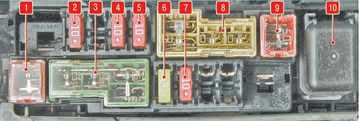
| № | Legend |
| 1 | 50A ABS Hydroelectronic Module |
| 2 | 10A Stop signal |
| 3 | 40A Ignition system, Glass lifters, ABS |
| 4 | 10A CVT control |
| 5 | 10A Sound signal generator |
| 6 | 20A Audio system, radio tape recorder |
| 7 | 10A CVT control |
| 8 | 60A Electric power steering, headlight washer (30A), ABS (30A) |
| 9 | 50A Radiator cooling fan |
| 10 | Horn relay |
Power fuse box #4
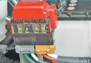
It is located on the positive terminal of the battery and is a group of fusible links that protect the fuse boxes in the passenger compartment and under the hood. On the diagrams it is marked with number 4. In case of complete absence of voltage, we recommend starting the test with them.
