Nissan Teana has been produced from 2003 to the present. The J31, the first generation, was produced in 2004, 2005, 2006, 2007 and 2008. Second generation j32 in 2009, 2010, 2011, 2012 and 2013, 2014. The third generation j33 was produced in 2014, 2015, 2016, 2017, 2018, 2019. Each of them has been restyled. In our material you will find a description of Nissan Teana fuses and relay blocks for second generation of the car, as well as their photos and diagrams. The fuse responsible for the “Cigarette lighter” is highlighted in bold.
Depending on the configuration, year of manufacture, and country of delivery, the design of the fuse boxes may differ from that described in this article. Please check the actual description on the back of your unit's protective cover.
In the passenger compartment
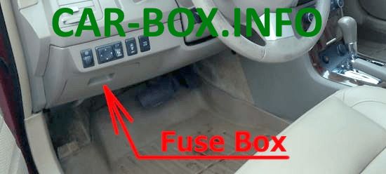
Located in the dashboard, behind the glove compartment.
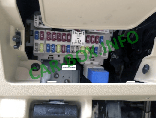
The photo.
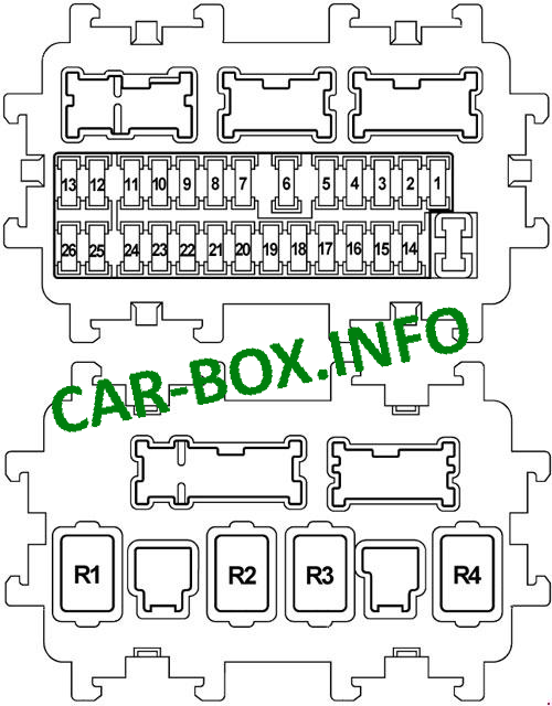
| Diagram | |
|---|---|
|
|
| № | Legend |
| 1 | 15A Heated front seats |
| 2 | 10A Airbags |
| 3 | 10A ASCD switch, Brake light switch, Headlight range control, Diagnostic socket, Air conditioning control unit, Steering wheel angle sensor, Body electronics control unit (BCM), Heated seat switch, Gas sensor, Ionizer, Rear curtain, Front seat ventilation switch, Rear seat ventilation switch, Seat ventilation unit, Engine mountings |
| 4 | 10A Instrument Cluster, Transmission Selector, Reverse Lamp Relay, AV Module |
| 5 | 10A Fuel filler cap |
| 6 | 10A Diagnostic connector, Air conditioning, Key connector, Key buzzer |
| 7 | 10A Brake lights, Body Control Module (BCM) |
| 8 | Not used |
| 9 | 10A Key connector, Start button |
| 10 | 10A Seat Memory, Body Control Module (BCM) |
| 11 | 10A Instrument panel, transmission control unit |
| 12 | Spare fuse |
| 13 | Spare fuse |
| 14 | Not used |
| 15 | 10A Heated mirrors, Air conditioning |
| 16 | Not used |
| 17 | 20A Heated rear window |
| 18 | Not used |
| 19 | Not used |
| 20 | Cigarette lighter |
| 21 | 10A Audio system, Display, BOSE audio system, Body control module (BCM), Multifunction switch, DVD player, Mirror switch, AV module, Navigation unit, Camera, Rear passenger switch box, Air conditioning |
| 22 | 15A Socket |
| 23 | 15A Heater relay |
| 24 | 15A Heater relay |
| 25 | Spare fuse |
| 26 | Not used |
| R1 - Ignition relay | |
| R2 - Rear window heating relay | |
| R3 - Relay additional equipment | |
| R4 - Heater relay | |
In the engine compartment
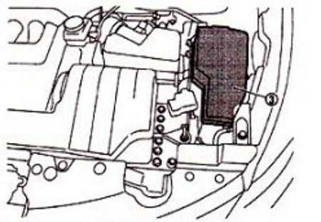
The two main distribution boxes are located on the left side, under a protective cover.

The photo.
Fuse panel #1
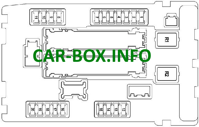
Diagram.
| № | Description |
| 1 | 15A Fuel pump relay, Fuel pump with fuel level sensor |
| 2 | 10A Cooling fan relay 2,3, Transmission selector |
| 3 | 10A Speed sensor (primary, secondary), Transmission control unit |
| 4 | 10A Engine control unit, Injectors |
| 5 | 10A Yaw rate sensor, ABS |
| 6 | 15A Lambda Sensor, Heated Oxygen Sensor |
| 7 | 10A Washer pump |
| 8 | 10A Steering column |
| 9 | 10A A / C relay, A / C fan |
| 10 | 15A Ignition coils, Solenoid valve 1,2 of VIAS system, Solenoid valve for timing control system, Condenser, Engine control unit, Mass air flow sensor, Canister purge solenoid valve |
| 11 | 15A Engine control unit, Throttle valve |
| 12 | 10A Headlight range control, Front side lights |
| 13 | 10A Tail lights, Interior lighting, License plate light, Glove box lamp, Rear curtain switch (front / rear), Rear passenger switch block, Seat ventilation switch, Heated seat switch, Door handle light, VDC switch, Headlight range control switch, Air conditioning, Trunk release button, Multi function switch, Combination switch, Hazard switch, Audio system, AV module, Lighting control, DVD player, Headlight range control, Navigation unit, Mirror switch |
| 14 | 10A High beam on the left side |
| 15 | 10A High beam, right side |
| 16 | 15A Low beam on the left side |
| 17 | 15A Low beam on the right side |
| 18 | 15A Front fog lamps |
| 19 | Not used |
| 20 | 30A Windscreen wiper |
| R1 - Cooling fan relay 1 | |
| R2 - Starter relay | |
Fuse panel #2
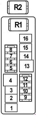
Diagram.
| № | Description |
| 1 | 40A Cooling fan |
| 2 | 40A Ignition relay, Fuse and relay box, Fuses: 1, 2, 3, 4 (passenger compartment fuse box) |
| 3 | 40A Cooling fan relay 2,3 |
| 4 | 40A Headlight washer |
| 5 | 15A Rear seat ventilation |
| 6 | 15A Sound signal |
| 7 | 10A Generator |
| 8 | 15A Ventilation of the front seat |
| 9 | Not used |
| 10 | 15A Audio system |
| 11 | 15A Bose audio system |
| 12 | 15A Audio system, Display, DVD player, AV module, Navigation unit, Camera |
| 13 | 40A Body Control Module (BCM) |
| 14 | 40A ABS |
| 15 | 30A ABS |
| 16 | 50A VDC |
| R1 - Horn relay | |
| R2 - Cooling fan relay | |
High power fuses
They are located on the positive terminal of the battery.
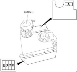
- A - 250A Starter, Alternator, Fuse No. B, C
- B - 100A Engine compartment fuse box (no. 2)
- C - 60A Front fog lights, High beam relay, Low beam relay, Side light relay, Fuses: 18 - front fog lights, 20 - wiper (engine compartment fuse box (no. 1))
- D - 100A Heater relay, Heated rear window relay, Fuses: 5, 6, 7, 9, 10, 11 (passenger compartment fuse box)
- E - 80A Ignition Relay, Fuses: 8, 9, 10, 11 (Engine Compartment Fuse Box (# 1))
