
The second-generation Peugeot 2008 was unveiled in 2019 in Aubervilliers. Completely redesigned inside and out, the model is now also offered with a fully electric powertrain. The vehicle is 14 cm longer, features a 6 cm longer wheelbase, and boasts an expanded boot capacity of 434 litres. In this article, we provide detailed fuse box diagrams and terminal assignments for the Peugeot 2008 (second generation; internal code P24) manufactured in 2019, 2020, 2021, 2022, 2023, 2024, and 2025.
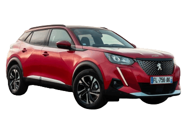
Below you will find the locations, diagrams, and reference photos for the power distribution blocks. The fuses designated for the "Cigarette lighter / 12V power outlet" and "Fuel pump" are highlighted in bold.
In the engine compartment

High-current maxi-fuses are located directly on the positive battery terminal.
| Diagram | ||
|---|---|---|

|
||
| No. | Description | Rating |
| 1 | Two-speed engine cooling fan control module | 60 A |
| 2 | Underhood main fuse box | 100 A |
| 3 | Electric power steering (EPS) module | 80 A |
| 4 | Cabin fuse box | 80 A |
| 5 | Cabin fuse box | 80 A |

The main engine compartment fuse box is situated on the right-hand side. Unclip and remove the protective cover to gain access.

The photo above illustrates a representative layout.
| Diagram | ||
|---|---|---|

|
||
| No. | Description | Rating |
| R1 | Engine management components / Euro 6 Diesel (SCR module power supply) | |
| R2 | A/C compressor clutch, Heated windscreen | |
| R3 | Starter motor, Glow plug preheating module | |
| R4 | Front fog lamps, Daytime running lights (DRL) | |
| R5 | A/C blower fan | |
| R6 | Starter motor | |
| R7 | Windscreen wipers (Front) | |
| R8 | Windscreen wipers (Front) | |
| R9 | Headlamps | |
| F1 | A/C blower fan motor | 40 A |
| F2 | ABS / ESP control module | 60 A |
| F3 | Cabin fuse box 3 | 80 A |
| F4 | ABS / ESP hydraulic unit module | 30 A |
| F5 | Body Control Module / BSI (Right indicators, RH front parking lights, RH brake lights, LH reversing light, RH fog lamp), Heated windscreen | 50 A / 20 A |
| F6 | Two-speed cooling fan control module (GMV), EAT8 automatic transmission ECU (AxN8), EAT6 automatic transmission ECU (Ax6III) | 60 A / 20 A |
| F7 | Body Control Module (BSI / Built-in Systems Interface) | 70 A |
| F8 | Fuel pump control module, Thermostat valve solenoid, Variable displacement oil pump solenoid (engine flush solenoid, intake airflow meter, oxygen sensors [EP6FADTX], switchable coolant pump solenoid [EP6FDT]), Engine Control Module (EB2DT / EP6FDT), Variable fuel feed pump (DV6F / DW10F) | 15 A / 20 A |
| F9 | Electronic fuel feed pump (DW10F), Intake and exhaust VVT solenoids, Thermostat valve solenoid, Variable displacement oil pump solenoid, Intake airflow meter, Oxygen sensors (EP6FADTX), Switchable coolant pump solenoid (EP6FDT) | 15 A |
| F10 | Engine management components — Diesel fuel metering solenoid valve, Turbocharger boost pressure control valve (DV5R / DW10F), Thermostat sensor (DV5R), Canister purge heater, Variable valve timing solenoids (EP6FADTX), EVAP canister purge valve, Upstream oxygen sensors (EB2ADTS) | 15 A |
| F11 | Engine Management System (EMS) components | 20 A |
| F12 | Instrument cluster, Cooling fan relay (GMV), Stop-Start system (i-StARS), DMTC, Auxiliary electric water pump for turbocharger (EB2ADTS / EP6FADTX), Body Control Module (EP6FADTX) | 5 A |
| F13 | Body Control Module (BSI) | 5 A |
| F14 | Battery Monitoring Unit (BMU / BECB) | 5 A |
| F15 | Front fog lamps / Daytime running lights (DRL) | 15 A / 10 A |
| F16 | Heated windscreen element | 20 A |
| F17 | OBD diagnostics: GMP BFRM, BSI1, Engine ECU, Downstream NOx sensor (DV5R / DW10F), Fuel injectors (DV5R) | 10 A |
| F18 | RH main beam headlamp | 10 A |
| F19 | LH main beam headlamp | 10 A |
| F20 | Engine ECU — Electric fuel pump (EP6FDT) / Ignition coils (EB2ADTS / EP6FADTX) | 30 A |
| F21 | Starter motor solenoid | 30 A |
| F22 | Taxi / Commercial fleet auxiliary reserve power supply | 40 A |
| F23 | Starter-generator module | 40 A |
| F24 | Cabin fuse box 5 | 40 A |
| F25 | Cabin fuse box 3 | 40 A |
| F26 | Cabin heater / HVAC blower circuit | 15 A / 20 A |
| F27 | Body Control Module (RH dipped beam headlamp, RH reversing light, LH fog lamp, LH rear position light, High-mounted third brake light) | 25 A |
| F28 | AdBlue heater and urea dosing pump module (DV5R BlueHDi), NOx sensor (DW10F), Engine Control Unit (EP6FADTX) | 30 A |
| F29 | Windscreen wiper motor | 40 A |
| F30 | Glow plug preheating control unit | 80 A |
| F31 | Engine compartment switching and protection unit (BSM) | 80 A |
| F32 | Electric Power Steering (EPS), LH dipped beam headlamp, Cornering lamps, Side repeater indicators, LH indicators, LH front / RH rear position lamps, LH brake light, Number plate lamps | 80 A |
In the passenger compartment

The cabin fuse panels are situated under the dashboard behind the glovebox housing.

Overview of the primary cabin power distribution panel.
| Diagram | |
|---|---|

|
|
| No. | Description |
| 1 | Auto-dimming rear-view mirror / Electric steering column adjustment / Advanced Grip Control switch / Forward radar / DeNOx SCR system |
| 3 | Wireless smartphone charging pad |
| 4 | Dual-tone horn |
| 5 | Windscreen and rear window washer pump |
| 6 | Windscreen and rear window washer pump |
| 7 | Rear passenger USB charging ports |
| 8 | Rear window wiper motor |
| 10 | Central locking / Tailgate latch motor |
| 11 | Central locking / Tailgate latch motor |
| 12 | Stop-Start system module, OBD-II diagnostic port, Brake System Control Module |
| 13 | Infotainment head unit, Automatic climate control module |
| 14 | Anti-theft alarm siren |
| 15 | HVAC / Climate control panel |
| 16 | Stop-Start system control unit, ABS / ESP module |
| 17 | Digital instrument cluster |
| 18 | Parking distance control (PDC) module |
| 19 | Steering column switch cluster (COM2000), Multifunction steering wheel controls |
| 21 | Intrusion alarm system |
| 22 | ADAM driver assist camera, Rain / Light sensor, Automatic headlamp control |
| 23 | Seat belt reminder (SBR) system module |
| 24 | 7-inch touchscreen, Active Park Assist, 360° Vision camera system |
| 25 | Supplemental Restraint System (SRS) Airbag ECU |
| 26 | Electronic Stability Control (ESC) module |
| 27 | Anti-theft alarm system |
| 28 | Autonomous Telematics Box (BTA) / OnStar Module |
| 29 | Infotainment system / Audio unit |
| 32 / 31 | Front centre console cigarette lighter and 12V auxiliary power socket |
| 34 | Heated rear window, Heated windscreen, Inductive charging module |
| 35 | Master lighting switch, OBD2 diagnostic connector |
| 36 | Interior ambient lighting / Courtesy lamps |

An auxiliary relay and fuse block is located directly behind the main cabin distribution panel.
| Diagram | ||
|---|---|---|

|
||
| No. | Description | Rating |
| R1 | Heated front seats relay | |
| R2 | Electric window lifters relay | |
| R3 | Cabin heater blower and heated rear window relay | |
| R4-R7 | Unassigned / Spare | |
| F1 | Heated rear screen element | 40 A |
| F2 | Heated exterior door mirrors | 10 A |
| F3 | Front power windows | 30 A |
| F4 | Power-folding exterior mirrors, Power mirror adjustment switch | 10 A / 15 A |
| F5 | Rear power windows | 30 A |
| F6 | 12V luggage compartment socket, Electric sunroof module | |
| F7 | Unassigned / Spare | |
| F8 | Dashboard right-hand fuse box link | |
| F9 | Unassigned / Spare | |
| F10 | Heated front seats element | 20 A |
| F11 | Front seat massage system | 20 A |
| F12 | Hi-Fi audio system amplifier module | 25 A |
