The 5008 is the first compact van produced under the Peugeot brand. It was first presented in September 2008 at the Paris Motor Show. In this article, we will take a detailed look at the fuse box diagrams for the Peugeot 5008 (1st generation; codename T8) 2009, 2010, 2011, 2012, 2013, 2014, 2015, 2016, 2017 years of manufacture.

Here you will find the locations and photos of distribution boxes. The fuses responsible for the “Cigarette lighter” and “Fuel Pump” are highlighted in bold.
In the passenger compartment
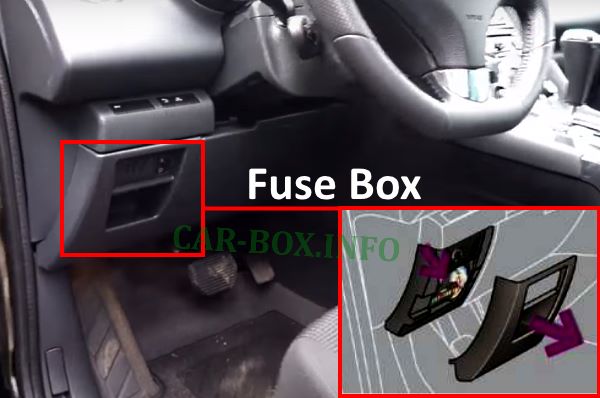
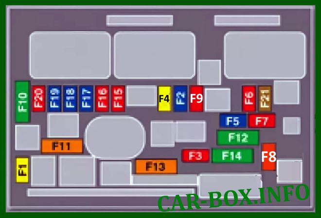
Located on the driver's side, behind the dashboard. To access it, pull the cover downwards.

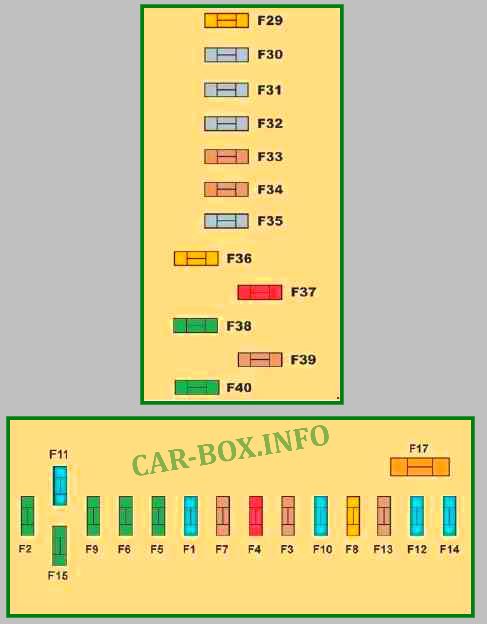
General view of the Peugeot 5008 interior fuse box.
| Diagram | ||
|---|---|---|
|
||
| No. | Decoding | A |
| F1 | Rear window wiper | 15 |
| F2 | Empty | - |
| F3 | Airbag ECU | 5 |
| F4 | Interior rear view mirror, air conditioning, security system switchgear, rear multimedia devices | 10 |
| F5 | Front power windows | 30 |
| F6 | Rear power windows | 30 |
| F7 | Front and rear interior lighting, rear spotlights, mirror illumination on sun visors, glove box illumination, center armrest illumination, 12 V luggage compartment relay circuit | 5 |
| F8 | Car stereo, radiotelephone, CD changer, multifunction display, tire pressure monitoring system, security alarm siren, security alarm ECU, telematics ECU | 20 |
| F9 | 12V socket front and rear, Peugeot 5008 cigarette lighter fuse | 30 |
| F10 | Thumbwheel switches | 15 |
| F11 | Ignition switch low current circuit | 15 |
| F12 | Trailer sensor, rain / light sensor, fuses F32, F34, F35 power supply | 15 |
| F13 | Engine ECU, Airbag ECU | 5 |
| F14 | Instrument panel, instrument panel display, fuse F33 power supply | 15 |
| F15 | Locking the locks and superlocking | 30 |
| F17 | Rear window heater, fuse supply F30 | 40 |
| SH | PARC shunt | - |
| F29 | Empty | - |
| F30 | Heated exterior rearview mirrors | 5 |
| F31 | 12V socket in trunk | 30 |
| F32 | Sequential gearbox lever | 5 |
| F33 | Head-up view panel, hands-free phone system, air conditioning | 10 |
| F34 | Seat belt indicator lamps | 5 |
| F35 | Parking assistance system, Hi-Fi amplifier | 10 |
| F36 | Trailer ECU processor, driver's door panel | 10 |
| F37 | Hi-Fi amplifier | 20 |
| F38 | Driver's power seat adjustment | 30 |
| F39 | Panoramic sunroof cover | 20 |
| F40 | Empty | - |
In the engine compartment
There are two distribution boxes here that are responsible for protecting the electrical circuits.
Main Fuse Box
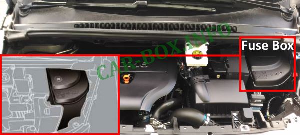
The main distribution box is located near the battery. It consists of two parts: the main board on top, and the MAXI power fuses on the side.
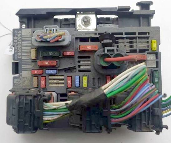
General view.
| Diagram | ||
|---|---|---|
|
||
| No. | Description | A |
| F1 | Power supply to engine ECU, solenoid valves of the fuel injector and EGR (on 2 L HDI engine), injectors (on 2 L HDI engine) | 20 |
| F2 | Horn (beep) | 15 |
| F3 | Front and rear window washer | 10 |
| F4 | Daytime Running Lights | 10 |
| F5 | Solenoid adsorber relief valves, electric turbocharger pressure reducing valve (on 1.6 l TNR engine), oil vapor heater (1.6 l TNR), diesel fuel heater (1.6 l HDI) | 15 |
| F6 | Diagnostic connector, adaptive headlights, particulate filter additive pump (on diesel), Distance Alert interval sensor, engine coolant level sensor, power mirrors | 10 |
| F7 | Power steering ECU, automatic transmission, adaptive headlamp controller actuator | 10 |
| F8 | Starter switch | 20 |
| F9 | Clutch and brake pedal contactors | 10 |
| F10 | Electronic engine management system components (on gasoline: ignition coils, solenoid valves, oxygen sensors, injectors, heating system components, fuel module (Peugeot 5008 fuel pump fuse), electronic thermostat; on diesel: solenoid valves, heating system components) | 30 |
| F11 | Air conditioning fan | 40 |
| F12 | Low/high speed of the windscreen wiper | 30 |
| F13 | Power supply of the intelligent switching unit (+ from the ignition switch) | 40 |
| F14 | Turbocharger pressure solenoid valve | 30 |
| F15 | High beam headlight, right | 10 |
| F16 | Left high beam headlamp | 10 |
| F17 | Left dipped beam headlamp | 15 |
| F18 | Right dipped beam headlamp | 15 |
| F19 * | Oil vapor heater (1.6 l VTI), turbo boost pressure regulator solenoid valve (on diesel), coolant level sensor (on diesel) | 15 |
| F20 | Electronic thermostat, fuel control solenoid valves, turbo boost pressure control solenoid valve (diesel), coolant level sensor (diesel) | 10 |
| F21 | Engine cooling fan relay power supply, Valvetronic relay switch (1.6 l VTI), turbo supercharger cooling (1.6 l TNR), air flow sensor (1.6 l HDI) | 5 |
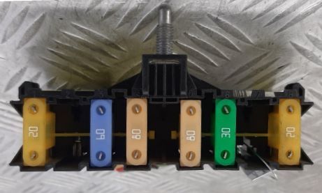
| Side plate with "MAXI" fuses | ||
|
||
| MF1 | Empty | |
| MF2 | ECU of the trailer electric circuit. | 30 |
| MF3 | Interior fuse box. | 50 |
| MF4 | Intelligent switching unit. | 80 |
| MF5 | 80 | |
| MF6 | Electric parking brake. | 30 |
| MF7 | Heated front seats. | 30 |
| MF8 | Headlight washer. | 20 |
Battery Power Box
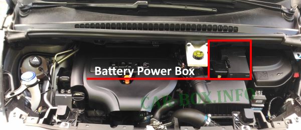
Additionally, a power board is mounted on the battery. It consists of fuses and high-capacity fusible links.
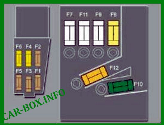
| Diagram | ||
|---|---|---|
|
||
| No. | Decoding | A |
| F1 | Empty | - |
| F2 | Dual function brake system contactor. | 5 |
| F3 | Battery charging system ECU. | 5 |
| F4 | ABS / ESP solenoid valves. | 25 |
| F5 | ABS / ESP ECU. | 5 |
| F6 | Automatic transmission and sequential transmission ECU. | 15 |
| F7 | Power steering electric pump. | 80 |
| F8 | Engine cooling fan. | 60 |
| F9 | Preheating system ECU (on diesel), Valvetronic electric actuator (1.6 l THP). | 80/30 |
| F10 | Electric pump of the ABS / ESP system. | 40 |
| F11 | Protection system switching unit. | 100 |
| F12 | Sequential transmission electric pump. | 30 |
