Peugeot 607 is a business class car produced from 1999 to 2010. 607 was introduced in 1999 as a replacement for the outdated 605 model. In this article, we will take a detailed look at the fuse box diagrams for the Peugeot 607 (1st generation; body 9D) 1999, 2000, 2001, 2002, 2003, 2004 and 2005, 2006, 2007, 2008, 2009, 2010 years of manufacture.
Here you will find the locations and photos of distribution boxes. The fuses responsible for the “Cigarette lighter” and “Fuel Pump” are highlighted in bold.
In the passenger compartment
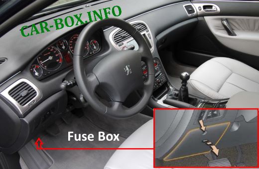
The main distribution box is located on the driver's side, at the bottom of the dashboard. The protective cover must be hinged to gain access.
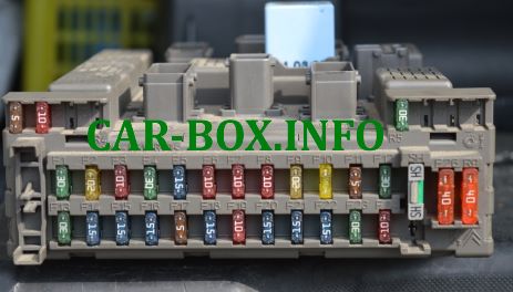
Type 1
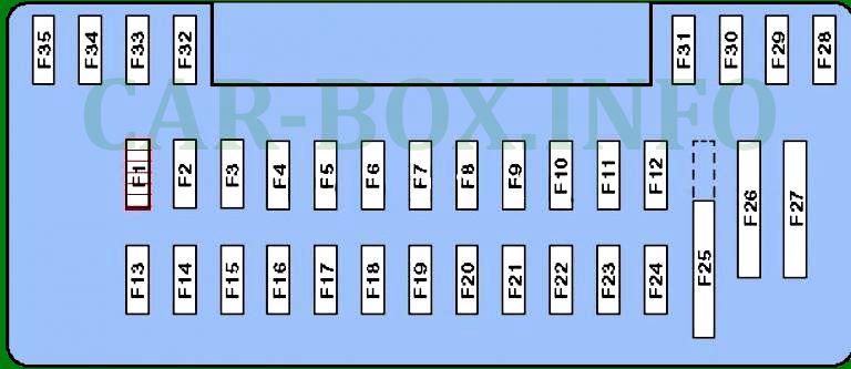
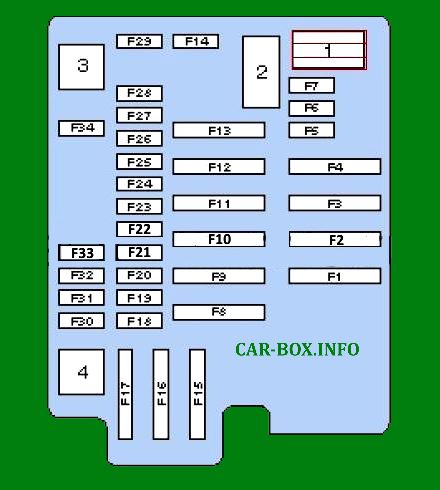
General view of the Peugeot 607 cabin fuse box.
| Diagram | ||
|---|---|---|

|
||
| No. | Description | A |
| F1 | Windshield washer pump and washer fluid level sensor | 15 |
| F2 | Weight of the electric circuit of the locking and superlocking system | 30 |
| F3 | Safety Airbags | 5 |
| F4 | Clutch pedal contactor, dual-function brake system contactor, diagnostic connector, ESP dynamic stabilization system sensor, light-sensitive rearview mirror | 10 |
| F5 | Power supply to front windows and sunroof vent | 30 |
| F6 | Rear power windows | 30 |
| F7 | Glove box contactor, interior general lighting lamps, individual lighting lamps, make-up mirrors | 5 |
| F8 | Power supply of multifunction display, paddle switch unit, siren of security alarm system, power supply of trailer switching unit, car radio RD4, radio telephone GPS RT3, control units of electric mirrors and all power windows | 20 |
| F9 | Peugeot 607 front and rear cigarette lighters | 30 |
| F10 | Fuel additive tank computer power supply | 10 |
| F11 | Automatic transmission computer, automatic transmission selector contactor, ignition switch with anti-theft device | 15 |
| F12 | Power supply for trailer switch unit, hands-free headset, seat relay seat memory switch unit, rain and light sensor | 15 |
| F13 | Power supply for the engine switching unit | 5 |
| F14 | Power supply to parktronic switch, instrument panel, air conditioning, airbag and pyrotechnic pretensioner switch | 15 |
| F15 | Power supply for locking and super locking systems | 30 |
| F17 | Hi-Fi amplifier, heated exterior mirrors | 40 |
| additional board | ||
| F31 | Right brake light | 5 |
| F32 | Left brake light | 5 |
| F33 | Third brake light | 5 |
| F34 | Radiotelephone power supply circuit | 5 |
| F35 | Tire pressure monitor computer, CD changer | 5 |
| F36 | Passenger seat relay | 30 |
| F37 | Front passenger seat and right rear seat heating | 30 |
| F38 | Heated driver's seat and rear left seat | 30 |
| F39 | Driver seat relay | 30 |
| F40 | Diagnostic connector | 5 |
Type 2
General view.
| Diagram | ||
|---|---|---|
|
||
| No. | Description | A |
| F1 | central locking system | 30 |
| F2 | Audio system | 20 |
| F3 | Windshield washer | 30 |
| F4 | Rear power windows | 30 |
| F5 | Electronic anti-theft system, monochrome display or color display electronic control unit, instrument panel, electronic climate control unit, car stereo/radio telephone | 15 |
| F6 | Stop lights | 10 |
| F7 | switches, rear ashtray light bulb, front flasher, rear flasher, rear cigarette lighter, rear license plate illumination lights, headlight adjuster. | 10 |
| F8 | Diagnostic connector, electronic headlight regulator unit, radio remote lock control unit, cabin air temperature sensor, tire pressure monitoring unit. | 10 |
| F9 | Headlight washers | 20 |
| F10 | Glove box lamp, front cigarette lighter, front and rear reading lights, inside rearview mirror, power outside mirrors. | 20 |
| F11 | Automatic light activation unit, airbag system, automatic light activation circuit relay. | 5 |
| F12 | Rear power windows | 30 |
| F13 | Windshield wiper | 30 |
| F14 | Empty | - |
| F15 | Power windows | 10 |
| F16 | Rear cigarette lighter fuse peugeot 607 | 15 |
| F17 | Heated door mirrors | 5 |
| F18 | Stop lights | 15 |
| F19 | Parking assist system unit, on-board navigation system unit | 10 |
| F20 | Siren, monochrome display or color display electronic control unit, radio remote control unit for locks, car radio/radio telephone, monochrome or color display unit for navigator, diesel fuel additive control unit. | 15 |
| F21 | Diagnostic connector, towed dwelling trailer wiring harness, trailer parking light relay | 15 |
| F22 | Diesel additive control unit, driver's seat memory unit, driver's door panel control key unit, front passenger's door panel control key unit | 15 |
| F23 | Driver's door power window, front passenger door power window, roof vent, passenger door power window keys on this door and on the driver's door. | 30 |
| F24 | Rear fog lights | 10 |
| F25 | Connector (jumper) | 40 |
| F26 | Electric rear window heater, radio antenna amplifier | 40 |
| F27-35 | Reserve | |
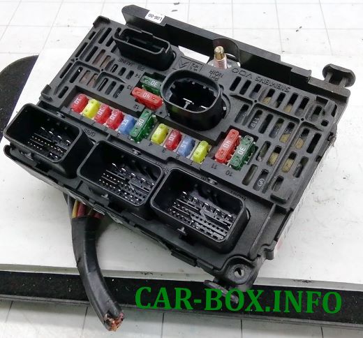
In the engine compartment
There are three distribution boxes here, which are responsible for protecting the vehicle's electrical circuits.
Fuse box
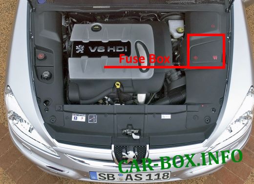
It is located on the left side behind the protective cover.
Type 1
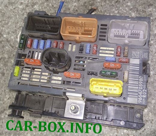
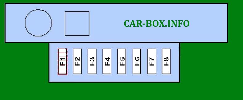
The photo shows an example.
| Diagram | ||
|---|---|---|

|
||
| No. | Decoding | A |
| F1 | Engine power system microprocessor. | 20 |
| F2 | Horn (beep) | 15 |
| F3 | Electric rear window shade. | 10 |
| F4 | Headlight washer. | 20 |
| F5 |
|
15 |
| F6 | Power steering, suspension ECU, automatic transmission, automatic headlight corrector unit. | 10 |
| F7 | Engine air flow sensor, ESP ECU. | 10 |
| F8 | Starter coil circuit. | 25 |
| F9 | Coolant level sensor, cabin heating system (HDI), brake signal contactor. | 10 |
| F10 | Components of the electronic engine management system (injectors, ignition coil, electrovalves, oxygen sensors ). | 30 |
| F11 | Air conditioning fan relay. | 40 |
| F12 | Wiper relay. | 30 |
| F13 | Power supply of the intelligent switching unit (+ from the ignition switch). | 40 |
| F14 | Turbocharger. | 30 |
| F15 | Right high beam headlamp. | 10 |
| F16 | Left high beam headlamp. | 10 |
| F17 | Left dipped beam headlamp. | 15 |
| F18 | Right dipped beam headlamp. | 15 |
| F19 |
|
15 |
| F20 | Diesel water sensor (on HDI 16V 2L and HDI 16V 2.2L), high pressure pump (on V6 HDI 24V 2.7L), turbocharger regulator solenoid valve (on HDI 16V 2L), distribution and exhaust system solenoid valves (on V6 24V 3L). | 10 |
| F21 | Engine cooling fan relay control, auxiliary fan relay control (on V6 HDI 24V 2.7 liter). | 10 |
Type 2
General view.
| Diagram | ||
|---|---|---|
|
||
| No. | Description | A |
| F1 | Intelligent switching unit (rear window heater, outside mirrors, window wiper, washer) | 70 |
| F2 | Cooling fan motor | 50 |
| F3 | ABS / ESP system | 50/60 |
| F4 | Air conditioner / heater fan motor | 40 |
| F5 | Horn (beep) | 20 |
| F6 | Seat Heater - Front Left and Rear Left | 20 |
| F7 | Seat Heater - Front Right and Rear Right | 20 |
| F8 | Intelligent switching unit. | 70 |
| F9 | Power seat | 30 |
| F10 | Dipped beam relay - automatic switching unit | 20 |
| F11 | Intelligent breakout box | 70 |
| F12 | Egnition lock. Anti-theft system power supply circuit. | 70 |
| F13 | Lighting control unit | 20 |
| F14 | Injection system dual relay power supply circuit | 15 |
| F15 | Empty | - |
| F16 | Empty | - |
| F17 | ABS / ESP system | 30 |
| F18 | Starter | 30 |
| F19 | Suspension control system | 20 |
| F20 | Engine cooling fan relay, auxiliary brake light switch, clutch and manual transmission sensor | 10 |
| F21 | Transmission control | 5 |
| F22 | ABS / ESP system | 25 |
| F23 | Diesel fuel heating unit | 15 |
| F24 | Engine management | 5 |
| F25 | Peugeot 607 fuel pump fuse | 10 |
| F26 | Power seat control unit | 30 |
| F27 | Relay box | 25 |
| F28 | Throttle heating circuit, electric injection control valve, flow meter, oil heating | 10 |
| F29 | Additive addition system | 10 |
| F30 | Empty | - |
| F31 | Transmission control | 5 |
| F32 | Electronic stability control system or ABS electronic unit | 10 |
| F33 | Electronic control unit for automatic transmission (except reversing lights) | 15 |
| F34 | Oxygen sensor, EGR valve, turbo boost pressure regulator valve. | 5 |
| 1 | Horn relay | |
| 2 | Starter relay | |
| 3 | Exhaust air pump relay | |
| 4 | Selector lock relay (range "P") | |
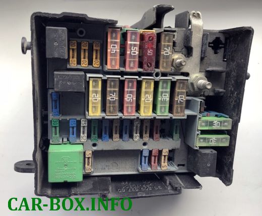
Type 3
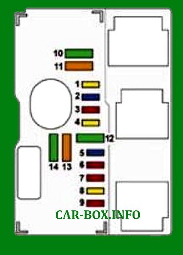
Diagram.
| No. | Appointment | A |
| 1 | Switching on the relay of the cooling system electric fan, auxiliary fan (for V6 HDI engine), engine computer power relay. | 20 |
| 2 | Horn (beep) | 15 |
| 3 | Front and rear washers. | 10 |
| 4 | Headlight washer. | 20 |
| 5 | Fuel pump and electric absorber relief valve. | 15 |
| 6 | Power steering, suspension ECU, automatic transmission. | 10 |
| 7 | Engine ECU, ESP ECU. | 10 |
| 8 | Starter winding circuit. | 15 |
| 9 | Level sensor, cabin heating (HDI), brake light contactor. | 10 |
| 10 | Engine control unit sensors (ignition coil, solenoid valves, oxygen sensors, computers, injectors). | 30 |
| 11 | Air conditioning fan relay. | 40 |
| 12 | Windshield wiper relay. | 30 |
| 13 | Power supply of the intelligent switching unit (+ from the ignition switch). | 40 |
| 14 | Turbocharger (on petrol engines). | 30 |
Auxilary fuse panels
Diagrams.
| Panel #1 | ||
|
||
| No. | Description | A |
| F1 | - | |
| F2 | Suspension control system | 20 |
| F3 | - | 80 |
| F4 | Air conditioner / heater fan motor | 40 |
| F5 | - | 80 |
| F6 | ABS / ESP system | 20 |
| F7 | 50 | |
| F8 | - | 80 |
| Panel #2 | ||
|
||
| F1 | Cooling fan motor | 50 |
| F2 | Glow plug control unit | 60 |
| F3 | Additional heater | 80 |
| F4 | Cooling fan motor | 50 |
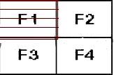
In the trunk

Located behind the left luggage compartment cover. Depends on equipment.
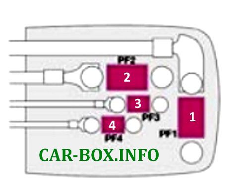
|
||
| No. | Appointment | A |
| 1 | Starter, alternator, cooling system switch, switching fuse box, engine cooling system electric fan, auxiliary electric fan (for V6 HDI engine). | 600 |
| 2 | Engine switching unit. | 150 |
| 3 | Rear window heater, trunk lid actuator switch, trunk latch, trailer switch box. | 60 |
| 4 | Trailer switch box (optional) | 30 |
General arrangement

General location of electronic components in the vehicle.
1. ABS electronic control module;
2. Electronic control module for air conditioner;
3. Air conditioner/heater fan motor control module;
4. Anti-theft system control module;
5. Battery;
6. Trunk lid opening/closing actuator control unit - in the right side of the luggage compartment;
7. Diagnostic connector (DLC);
8. Electronic Engine Management Module (EEM);
9, 10. Cooling fan motor relay;
11. Additive control module - in the right side of the luggage compartment;
12. Fuse/relay box, center console - Diesel;
13, 14, 15. Fuse box in the engine compartment;
16, 17. Fuse box in the passenger compartment;
18, 19. Fuse box in the trunk;
20. Glow plug control module;
21. Heater fan motor relay;
22, 23. Buzzer;
24. Instrument cluster control module;
25. Multifunction control unit 1 - integrated in fuse/relay box 1 of the instrument panel - functions: Central lock, rear window heater, immobilizer, turn indicators/emergency lights, brake lights, tail lights. windshield washer. windshield washer;
26. Multifunction control unit 2- integrated in fuse box/relay 1 in engine compartment- functions: Air conditioning system .cooling fan motor, engine management, fog lights, horn, windshield wipers;
27. Multifunction control unit 3- integrated in fuse box / relay 2 in luggage compartment - functions: Trailer electrical connector
28. Ambient air temperature sensor in the door rearview mirror;
29. Parking control module - in the right-hand side of the luggage compartment;
30. Power steering control module;
31. Power seat control module;
32. Steering column electrical control module;
33. SRS electronic control module;
34. Suspension control module;
35. Telephone control module;
36. Electronic transmission control module (TCM);
37. Tire pressure monitoring system control module - in the right-hand side of the luggage compartment.
