
The Peugeot Expert is a light commercial vehicle produced alongside the Citroën Jumpy and Fiat Scudo at the Sevel Nord joint-venture plant (PSA Group / Fiat Chrysler) in northern France since 1995. The second generation (Type G9 / VF3V platform) was produced from 2007 through 2016. This guide details the fuse box locations, circuit assignments, and fuse box diagrams for the Peugeot Expert 2nd gen (chassis code G9; Sevel Nord platform; 2007, 2008, 2009, 2010, 2011, 2012, 2013, 2014, 2015, and 2016 model years).
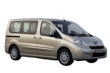
Below you will find fuse box locations, layout diagrams, and photos. The cigarette lighter fuse is highlighted in bold.
Passenger Compartment Fuse Boxes
There are three fuse blocks inside the cabin designed to protect the vehicle’s electrical circuits.
Main Cabin Fuse Box
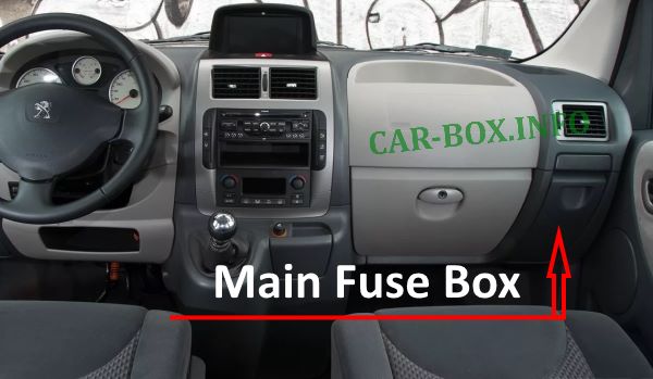
Located on the passenger side behind the glove box. To gain access, open the glove box lid, unhook the retaining tabs, and pull firmly downward.
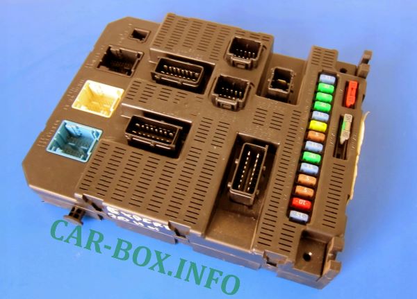
Peugeot Expert II main interior fuse box overview.
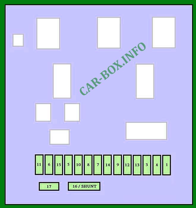
| Fuse Box Diagram | ||
|---|---|---|
|
||
| Fuse No. | Protected Component / Circuit | Rating (A) |
| 1 | Tailgate window wiper motor | 15 |
| 2 | Not used | - |
| 3 | Airbag control module (SRS ECU) | 5 |
| 4 | Steering angle sensor, OBDII diagnostic connector, ESP sensor module, HVAC controls, clutch pedal switch, headlamp leveling switch, diesel particulate filter (DPF) additive pump | 10 |
| 5 | Power heated door mirrors, passenger side power window motor | 30 |
| 6 | Front power window supply | 30 |
| 7 | Interior courtesy lamps, glove box lamp switch | 5 |
| 8 | Multi-function display screen, anti-theft alarm siren, audio head unit, CD changer, telematic unit, trailer control module, coachbuilder conversion ECU | 20 |
| 9 | Rear 12V auxiliary power outlet, Peugeot Expert 2 cigarette lighter fuse | 10 |
| 10 | Pneumatic rear suspension levelling control module, steering column stalk switch cluster (COM2000), instrument cluster | 30 |
| 11 | Data link connector (OBDII), ignition switch circuit | 15 |
| 12 | Bluetooth hands-free module, airbag ECU, rear parking assist module | 15 |
| 13 | Engine control unit (ECU), trailer interface unit | 5 |
| 14 | Rain/light sensor module, automatic climate control system, instrument panel controls | 15 |
| 15 | Central locking / unlocking control circuit | 30 |
| 16 | Not used | - |
| 17 | Heated rear screen and heated door mirrors | 40 |
| Heated door mirrors only | 10 | |
Auxiliary Fuse Panel #1
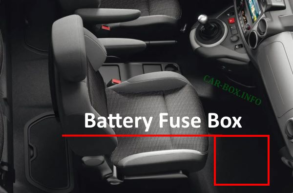
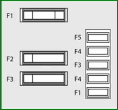
Located adjacent to the battery. Access is gained by removing the footwell floor trim panel on the front passenger side (LHD vehicles) or driver side (RHD vehicles).
| Fuse Box Diagram | ||
|---|---|---|
|
||
| Fuse No. | Protected Component / Circuit | Rating (A) |
| 1 | Heated seats control unit | 30 |
| 2 | Third-row 12V accessory power outlet (passenger van models) or Spare / unassigned (cargo van models) |
20 |
| 3 | Trailer interface module, bodybuilder/conversion ECU | 40 |
| 4 | Not used | |
| 36 | Sliding side door deadlocking system | 15 |
| 37 | 10 | |
| 38 | Rear window wiper / sliding door power window motor | 20 |
| 39 | Rear passenger cabin blower fan (passenger van models) or Not used (cargo van models) |
|
| 40 | Power-folding exterior mirrors unit | 5 |
Auxiliary Fuse Panel #2
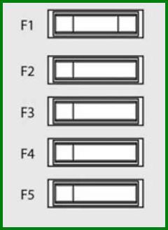
Located on the right-hand side behind the cargo area partition wall, housing trailer tow-bar electrical equipment fuses.
|
||
| Fuse No. | Protected Component / Circuit | Rating (A) |
| F1 | Spare / unassigned | 15 |
| F2 | Ignition switch feed to trailer module / secondary alternator charge circuit | 15 |
| F3 | Trailer socket 12V constant power supply circuit | 15 |
| F4 | Switched live auxiliary feed for conversion equipment | 15 |
| F5 | Hazard warning lights circuit | 10 |
Engine Compartment Fuse Box
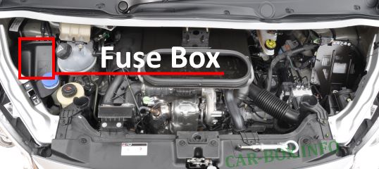
Located on the right side of the engine bay next to the windshield washer fluid reservoir.
| Peugeot Expert II Under-Hood Fuse Box Assignment | ||
|---|---|---|
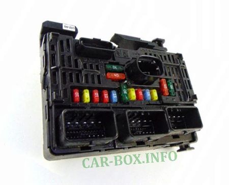
Under-hood unit photo. |
||

Fuse box diagram. |
||
| Fuse No. | Protected Component / Circuit | Rating (A) |
| 1 | Engine management ECU, sensors/actuators supply, air intake system components, radiator cooling fan relay | 20 |
| 2 | Dual-tone horn circuit | 15 |
| 3 | Windscreen and rear window washer pump assembly | 10 |
| 4 | Headlamp washer pump relay unit | 20 |
| 5 | Fuel pump and fuel injection system components | 15 |
| 6 | Electro-hydraulic power steering ECU, secondary brake pedal switch | 10 |
| 7 | ABS / ESP hydraulic control module supply | 10 |
| 8 | Starter motor solenoid circuit | 20 |
| 9 | Primary brake switch (stop lamp switch) | 10 |
| 10 | Engine actuators, air intake control valve, emissions control systems (EGR / DPF) | 30 |
| 11 | HVAC blower motor fan control module | 40 |
| 12 | Windshield wiper linkage motor | 30 |
| 13 | Built-in Systems Interface (BSI / Intelligent Switching Unit) main feed | 40 |
| 14 | Spare / unassigned | 30 |
