
Most electrical power circuits on this French crossover are protected by fuses. High-draw electrical components, such as the headlights, cooling fan motors, and fuel pump, are powered through relays. Fuses and relays are housed in distribution boxes located in the engine compartment and passenger compartment.
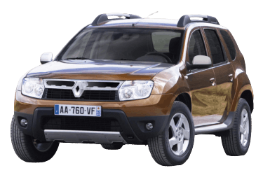
This article provides detailed fuse box diagrams and relay assignments for the 1st-generation Renault Duster (chassis codes HSA, HSM; B0 platform) produced from 2010 through 2015.
Passenger Compartment
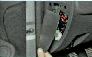
The passenger compartment fuse box is located on the driver's side end of the instrument panel, behind a plastic trim cover. To access it, remove the access panel on the side of the instrument panel.
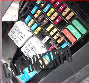
General view.

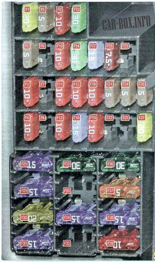
Fuse box cover legend.
| Diagram | ||
|---|---|---|
|
||
| No. | Rating (A) | Circuit Protected / Description |
| F1 | 20 | Windshield wiper motor, wiper switch, heated rear window relay |
| F2 | 5 | Instrument cluster, fuel pump relay, Engine Control Module (ECU), seat belt unbuckled warning lamp, airbag deactivation indicator |
| F3 | 10 | Brake light switch |
| F4 | 10 | Diagnostic connector (OBD2), immobilizer antenna module, automatic transmission selector unit, Body Control Module (BCM) |
| F5 | 5 | Automatic transmission control unit (TCU), starter relay, electronic transmission control unit |
| F6 | - | Spare |
| F7 | - | Spare |
| F8 | - | Spare |
| F9 | 10 | Instrument cluster, left low beam headlight |
| F10 | 10 | Right low beam headlight |
| F11 | 10 | Instrument cluster, left high beam headlight |
| F12 | 10 | Right high beam headlight |
| F13 | 30 | Rear power window motors |
| F14 | 30 | Front power window motors |
| F15 | 10 | ABS ECU, yaw rate/acceleration sensor, steering angle sensor |
| F16 | 15 | Heated front seats |
| F17 | 15 | Horn |
| F18 | 10 | Left front and rear parking lights / side markers |
| F19 | 10 | Right front and rear parking lights, glove box lighting, instrument cluster backlighting, hazard switch, HVAC control unit, audio system, cigarette lighter fuse, central locking switch, front power window switches, 4WD mode selector switch, license plate lights |
| F20 | 7.5 | Rear fog light |
| F21 | 5 | Heated door mirrors |
| F22 | - | Spare |
| F23 | - | Spare |
| F24 | 5 | Electro-hydraulic power steering pump (if equipped / not used) |
| F25 | 5 | LPG/CNG fuel system (if equipped / not used) |
| F26 | 5 | Airbag system (SRS) |
| F27 | 20 | Tailgate wiper motor, horn, top dead center (TDC) sensor, manual transmission reverse light switch |
| F28 | 15 | Body Control Module (BCM) (power-saving mode) |
| F29 | 15 | Body Control Module (BCM), diagnostic connector (OBD2) |
| F30 | 20 | Body Control Module (BCM) |
| F31 | 15 | Front fog lights, fog light relay |
| F32 | 30 | Heated rear window |
| F33 | - | Spare |
| F34 | 15 | Transmission Control Module (TCU) |
| F35 | - | Spare |
| F36 | 30 | HVAC blower motor |
| F37 | 5 | Power door mirrors |
| F38 | 15 | Audio system, cigarette lighter / 12V socket |
| F39 | 10 | HVAC blower motor relay |
Engine Compartment
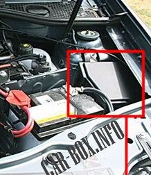
The engine compartment distribution box is located on the left side of the engine bay and is secured with a protective plastic cover.
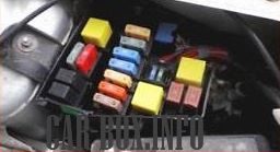
General view.
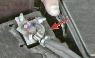
1) To access the engine compartment distribution box, press the cover latch ...

2) ... and remove the distribution box cover.
K4M Engine
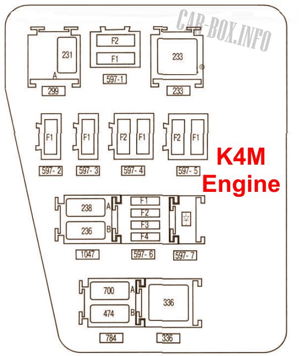
Diagram.
| No. | Function / Circuit Protected | |
| Panel 597-1 | ||
| F1 | ABS and ESP Control Unit | 50 |
| F2 | 25 | |
| Panel 597-2 | ||
| F1 | Radiator cooling fan, A/C compressor clutch | 50 40 |
| Panel 597-3 | ||
| F1 | Power steering pump | 80 |
| Panel 597-4 | ||
| F1, F2 | Exterior lighting switch | 60 |
| Panel 597-5 | ||
| F1 | Auxiliary interior heater, auxiliary heater relay (not used) | 80 |
| F2 | 4WD Transmission Control Unit | 25 |
| Panel 597-6 | ||
| F1 | Radiator cooling fan (low speed) | 30 |
| F2 | Fuel pump | 25 |
| F3 | Spare | |
| F4 | LPG/CNG fuel system (not used) | 25 |
| Relays | ||
| Diode | 597-7 A/C compressor clutch diode | |
| 231 (A) | Front fog lamps relay | |
| - (B) | Not used | |
| 233 | HVAC blower motor relay | |
| 238 (A) | Fuel injection lockout relay | |
| 236 (B) | Fuel pump relay | |
| 700 (A) | Radiator cooling fan relay (low speed) | |
| 474 (B) | A/C compressor relay | |
| 336 | Radiator cooling fan relay (high speed) | |
F4R Engine
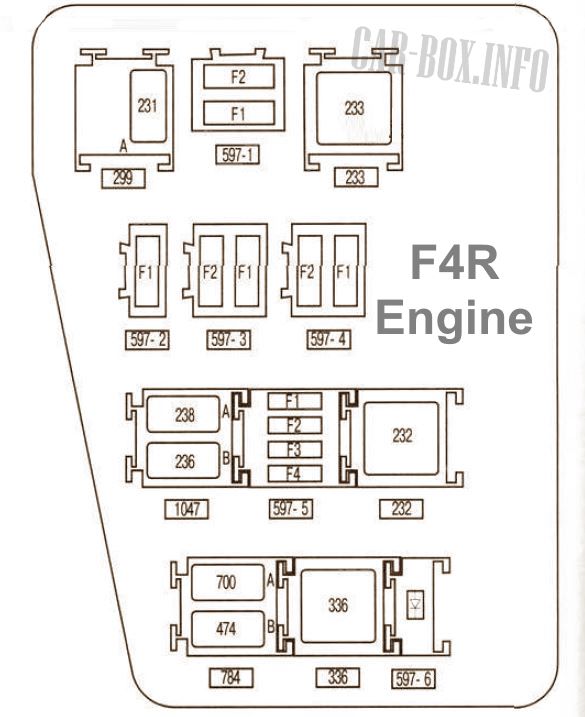
Diagram.
| No. | Circuit Protected / Description | Rating (A) |
| Panel 597-1 | ||
| F1, F2 | ABS and ESP Control Unit | 50/25 |
| Panel 597-2 | ||
| F1 | Radiator cooling fan, A/C compressor clutch | 50/40 |
| Panel 597-3 | ||
| F1, F2 | Exterior lighting switch | 60 |
| Panel 597-4 | ||
| F1 | Auxiliary interior heater, auxiliary heater relay | 80 |
| F2 | 4WD Transmission Control Unit | 25 |
| Panel 597-5 | ||
| F1 | Radiator cooling fan (low speed) / A/C compressor clutch |
15 30 |
| F2 | Fuel pump fuse | 25 |
| F3 (-) | Spare | - |
| F4 | Automatic transmission control unit (TCU) | 15 |
| Panel 597-6 | ||
| Diode | A/C compressor clutch diode | |
| Relays | ||
| 231 (A) | Front fog lamps relay | |
| - (B) | Not used | |
| 233 | HVAC blower motor relay | |
| 238 (A) | Fuel injection lockout relay | |
| 236 (B) | Fuel pump assembly | |
| 700 (A) | Radiator cooling fan relay (low speed) | |
| 474 (B) | A/C compressor relay | |
| 336 | Radiator cooling fan relay (high speed) | |
| 232 | Starter motor relay | |

Slt