Table of Contents
Most of the power supply circuits of the electrical equipment of the French crossover are protected by fuses. Headlights, fan motors, fuel pump and other powerful current consumers are connected via relays. Protective elements are installed in distribution boxes, which are located under the hood and in the passenger compartment.
Considered the Renault Duster diagrams of the 1st generation in restyling (HSA, HSM) 2016, 2017, 2018, 2019, 2020 model year.
In the engine compartment
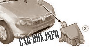
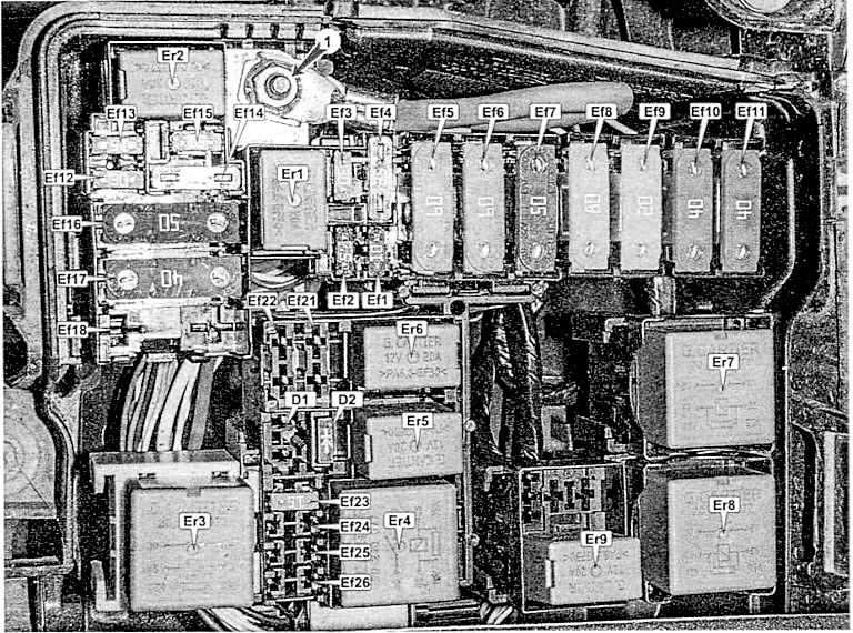
The fuse box is located on the left side of the engine compartment. It is closed with a plastic cover.

General view.
| Diagram | |
|---|---|
|
|
| № | Amps / Description |
| Ef1 | 10A Fog lights |
| Ef2 | 7.5A Electrical control unit |
| Ef3 | 30A Heated rear window, heaters outside mirrors |
| Ef4 | 25A Stability control unit |
| Ef5 | 60A Fuse circuits P11, P24-P27, P34, P39, P41 |
| Ef6 | 60A Ignition switch (lock), P28 fuse circuits. P31, P38, P43, P46, P47 |
| Ef7 | 50A Stability control unit |
| Ef8 | 80A Luggage compartment socket |
| Ef9 | 20A Reserve |
| Ef10 | 40A Heated windshield 1 |
| Ef11 | 40A Heated windscreen 2 |
| Ef12 | 30A Starter |
| Ef13 | 15A Reserve |
| Ef14 | 25A Electronic engine management system |
| Ef15 | 15A A / C compressor clutch relay, A / C compressor clutch |
| Ef16 | 50A Electro cooling fan |
| Ef17 | 40A Automatic gearbox control unit |
| Ef18 | 80A Electric power steering pump |
| Ef19 | Reserve |
| Ef20 | Reserve |
| Ef21 | 15A Oxygen concentration sensors, canister purge valve, camshaft position sensor, phase change valve |
| Ef22 | Electronic engine control unit (ECU), electric cooling fan control unit, ignition coils, fuel injectors, fuel pump |
| Ef23 | Fuel pump |
| Er1 | Horn relay |
| Er2 | Alarm relay |
| Er3 | Starter |
| Er4 | Engine managment |
| Er5 | A/C |
| Er6 | Fuel pump relay |
| Er7 | Heater front window / Cooling fan |
| Er8 | Front window heater |
| Er9 | Starter 2 |
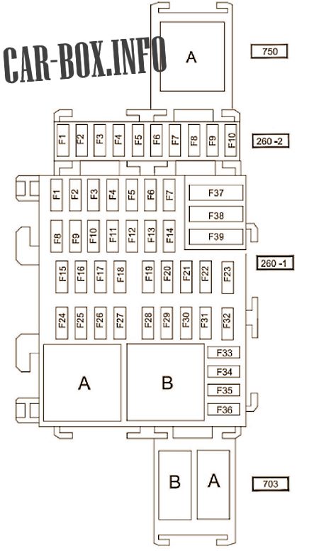
In the passenger compartment
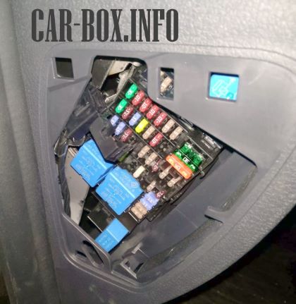
The distribution box is located on the driver's side. At the end of the dashboard, behind a plastic cover.
| Diagram | ||
|---|---|---|
|
||
| No. | Description | Amps |
| Panel 260-2 | ||
| F1 | Spare | |
| F2 | ECM, left headlamp, right headlamp | 25 |
| F3 | All-wheel drive transmission (4WD) | 5 |
| F4 | Spare / additional control unit for electrical equipment | 15 |
| F5 | Rear accessory connector ( female ) | 15 |
| F6 | Electrical control module | 5 |
| F7 | Spare | |
| F8 | Unknown | 7.5 |
| F9 | Spare | |
| F10 | Spare | |
| A | Locking rear power windows | |
| Panel 260-1 (main board) | ||
| No. | Decoding | Amps |
| F1 | Power window front door | 30 |
| F2 | High beam left headlight | 10 |
| F3 | High beam, right headlight | 10 |
| F4 | Left headlight low beam | 10 |
| F5 | Low beam, right headlight | 10 |
| F6 | Taillights | 5 |
| F7 | Front parking lights | 5 |
| F8 | rear door window lifter | 30 |
| F9 | Rear fog lamp | 7.5 |
| F10 | Horn | 15 |
| F11 | Automatic door lock | 20 |
| F12 | ABS systems (ABS) - ESC, brake light switch | 5 |
| F13 | Courtesy lamp, luggage compartment lighting, glove compartment lighting | 10 |
| F14 | Not | |
| F15 | Windshield wiper | 15 |
| F16 | Multimedia system | 15 |
| F17 | Fluorescent lamps | 7.5 |
| F18 | Stop signal | 7.5 |
| F19 | Injection system, instrument panel, central electronic switching unit in the passenger compartment | 5 |
| F20 | Safety bag | 5 |
| F21 | 4WD 4WD, reverse gear | 7.5 |
| F22 | Power steering | 5 |
| F23 | Cruise control / speed limiter, rear window relay, seat belt not fastened signal, parking distance monitoring system, relay for additional heating of the passenger compartment | 5 |
| F24 | UCH (passenger compartment central electronic connection unit) | 15 |
| F25 | 2 | |
| F26 | Direction indicators | 15 |
| F27 | Steering column switches | 20 |
| F28 | Klaxon | 15 |
| F29 | Steering column switches | 25 |
| F30 | Not | |
| F31 | Dashboard | 5 |
| F32 | 3Radio receiver, air conditioning control panel, interior ventilation, rear connector for connecting electrical accessories | 7.5 |
| F33 | Cigarette lighter fuse duster | 20 |
| F34 | Diagnostic connector and audio connector | 15 |
| F35 | Heated rearview mirror | 5 |
| F36 | Electric door mirrors | 5 |
| F37 | Interior central electronic switching unit, starter | 30 |
| F38 | Windshield wiper | 30 |
| F39 | Interior ventilation | 40 |
| A | air conditioner fan | |
| B | Heated mirrors | |
| Panel 703 | ||
| A | Additional socket in the luggage compartment | |
| B | Reserve | |

Very helpful
Foarte util
There is a signal lamp at the left of dashboard.it does lit but I don't know which part stands for.it look likes a w.