Renault Laguna 2nd generation was produced in 2001, 2002, 2003, 2004, 2005, 2006 and 2007. During this time, the car underwent a facelift: the radiator grille was slightly changed, and the handling and safety were also improved.
In this article you will find information on the location of all electronic control units, as well as a description of fuse and relay units for a Laguna (X74) 2nd generation car with diagrams and photographs.
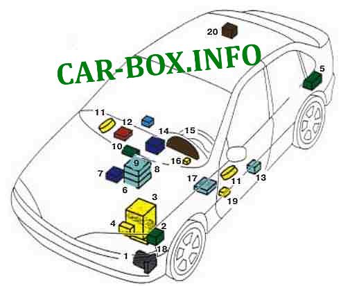
General arrangement
Location of all electronic control units.
|
|
| 1 | ABS computer and dynamic stabilization systems |
| 2 | Fuel injection computer |
| 3 | Accumulator battery |
| 4 | Automatic transmission computer |
| 5 | CD changer |
| 6 | Renault card reader |
| 7 | Central switching unit |
| 8 | Air conditioner computer |
| 9 | Radio and navigation equipment |
| 10 | Central display |
| 11 | Power window control unit |
| 12 | Speech synthesizer computer |
| 13 | Side impact sensor |
| 14 | Airbag computer |
| 15 | Dashboard |
| 16 | Steering wheel lock computer |
| 17 | Salon central unit |
| 18 | Battery discharge warning lamp corrector |
| 19 | Computer for storing adjustments of the driver's seat |
| 20 | Parking aid computer |
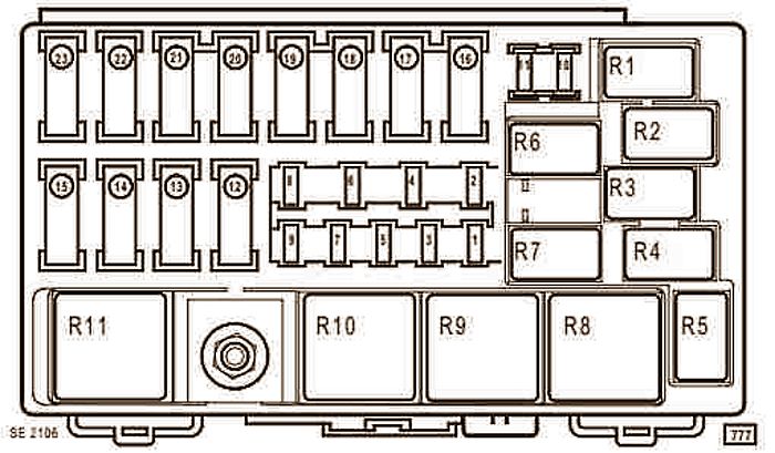
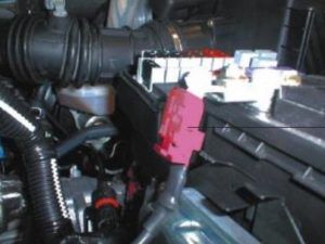
In the engine compartment
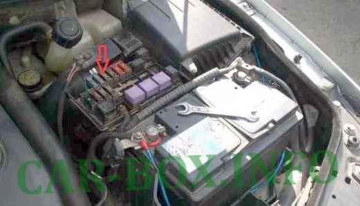
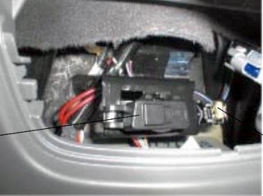
The main unit in the engine compartment is located next to the battery.
| Engine Fuse Box Diagram | |
|---|---|
|
|
| № | Amps / Description |
| 1 | (7.5A) Automatic transmission |
| 2 | Not Used |
| 3 | (30A) Engine management |
| 4 | (5A / 15A) Automatic transmission |
| 5 | (30A) Brake servo vacuum pump relay (F4Rt) |
| 6 | (10A) Engine management |
| 7 | Not Used |
| 8 | Not Used |
| 9 | (20A) Air conditioning system |
| 10 | (20A / 30A) Anti-lock braking system / stability control system |
| 11 | (20A / 30A) Buzzer (s) |
| 12 | Not Used |
| 13 | (70A) Coolant Heaters - If Equipped |
| 14 | (70A) Coolant Heaters - If Equipped |
| 15 | (60A) Cooling fan motor control |
| 16 | (40A) Headlamp washers, heated rear window, multifunction control module |
| 17 | (40A) Anti-lock braking system / stability control system |
| 18 | (70A) Combination switch, daylight system, multifunction control box |
| 19 | (70A) Heater / air conditioner, multifunction control unit |
| 20 | (60A) Battery current monitor relay (some models), combination switch (some models), daytime running lights, multifunction control box |
| 21 | (60A) Power seats, multifunction control module, fuse / relay box, center console, sunroof |
| 22 | (80A) Heated windshield (some models) |
| 23 | (60A) Windshield wiper, electric parking brake |
| № | Relays (Type 1) |
| R1 | Coolant heater relay |
| R2 | Cooling fan motor relay (without A / C) |
| R3 | Not used |
| R4 | Not used |
| R5 | Brake servo vacuum pump relay |
| R6 | Fuel pump relay |
| R7 | Diesel heater relay |
| R8 | Fuel interlock relay |
| R9 | A / C Fan Low Speed Relay |
| R10 | Air conditioner fan relay |
| R11 | Thermoplunger relay 2 |
| № | Relays (Type 2) |
| R1 | Not used |
| R2 | A / C Fan Low Speed Relay |
| R3 | Not used |
| R4 | Not used |
| R5 | Not used |
| R6 | Fuel pump relay |
| R7 | Heater relay (fuel gas ventilation system) |
| R8 | Fuel pump relay |
| R9 | A / C Fan Low Speed Relay |
| R10 | A / C blower motor relay |
| R11 | Not used |
The entire electrical circuit is protected by a main fuse located on the positive battery cable.
In the passenger compartment
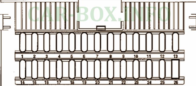
Primary fuse box
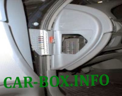
Located on the left side at the end of the dashboard.

The relay board (2) is connected to it.
General view.
| Main box diagram | ||
|---|---|---|
|
||
| No. | Description | Amps |
| 1 | High beam headlights | 20 |
| 2 |
|
10 |
| 3 |
|
10 |
| 4 | Reversing lights - Heating and air conditioning - Parking assistance - + Signal after ignition of the burglar alarm - Electric lock switch lighting - Rain sensor - Heated windshield | 20 |
| 5 | Delayed interior lighting | 15 |
| 6 | Brake lights - Wiper switch - Diagnostic socket - Tire pressure monitor warning lamp - Child safety warning lamp - Rear door electric lock warning lamp - Power window switch lights | 20 |
| 7 | Left headlight low beam | 15 |
| 8 | Right side lights | 7.5 |
| 9 | Direction indicators for direction indication and hazard warning | 15 |
| 10 | Communication System - Car Radio | 10 |
| 11 |
|
30 |
| 12 | Airbags and seat belt pretensioners | 5 |
| 13 |
|
5 |
| 14 | Sound signal (horn) | 15 |
| 15 | Power window driver's door | 30 |
| 16 | Passenger door power window | 30 |
| 17 | Rear fog lights | 10 |
| 18 | Heated exterior mirrors | 10 |
| 19 | Low beam, right headlight | 15 |
| 20 |
|
7.5 |
| 21 | Windscreen and rear window wipers | 30 |
| 22 | Electric central locking | 30 |
| 23 |
|
15 |
| 24 |
|
15 |
| 25 |
|
10 |
Relay box
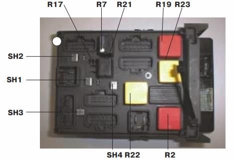
Diagram.
| No. | Decoding |
| SH1 | Rear door power window shunt |
| SH2 | Front Power Window Shunt |
| SH3 | Headlamp low beam shunt |
| SH4 | Parking light circuit shunt |
| R2 | Heated rear window |
| R7 | Front fog lights |
| R9 | Windshield wipers |
| R10 | |
| R11 | Rear window wiper / reversing lights |
| R12 | Locking doors |
| R13 | |
| R17 | Rear window wiper |
| R18 | Temporary activation of interior lighting |
| R19 | Additional electrical equipment |
| R21 | Engine start interlock |
| R22 | "Plus" after ignition switch |
| R23 | Accessories / optional audio system / rear door power windows |
Seperate fuse
A separate 20 Amp fuse is located under the ashtray in the center console.
Protects circuits:
- Car radio;
- ECU of the air conditioner;
- ECU of the system of storing the position of the seats;
- Diagnostic connector;
- ECU of the navigation system;
- ECU of the tire pressure monitoring system;
- Combined display (clock / outside temperature / car radio);
- Central communication block;
- ECU of the system of storing the position of the seats;
- Circuits of connection with the alarm system
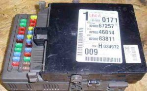
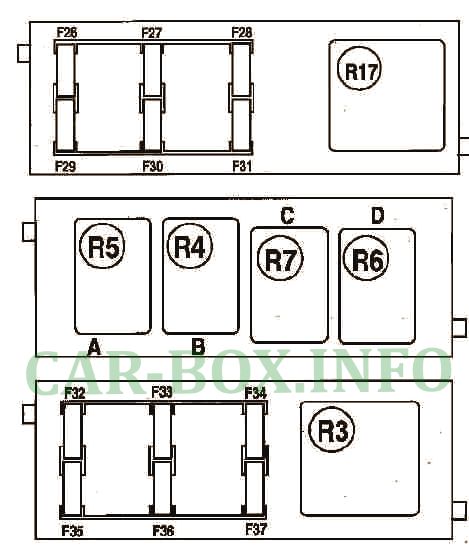
Auxilary fuse box

On the passenger side, behind the glove compartment, there is an additional fuse box.
| diagram | ||
|---|---|---|
|
||
| No. | Description | Amps |
| F26 | Trailer electrical connector | 30 |
| F27 | Sunroof | 30 |
| F28 | Power window regulator, left rear | 30 |
| F29 | Power window regulator, right rear | 30 |
| F30 | Steering wheel position sensor | 5 |
| F31 | Empty | - |
| F32 | Empty | - |
| F33 | Empty | - |
| F34 | seat heating for driver and passenger | 20 |
| F35 | Heated front seats | 20 |
| F36 | Power Seat - Driver Side | 20 |
| F37 | Power passenger seat | 20 |
| 17 | Power window relay | |
| 3 | Power seat relay | |
| 4 | Daytime running headlight warning lamp relay | |
| 5 | Daytime running light relay | |
| 6 | Headlight washer pump relay | |
| 7 | Brake light cut-off relay | |
